Subaru Impreza 3 / Impreza WRX / Impreza WRX STI. Service manual — part 153
IN(w/o STI)-11
Intake Duct
INTAKE (INDUCTION)
5. Intake Duct
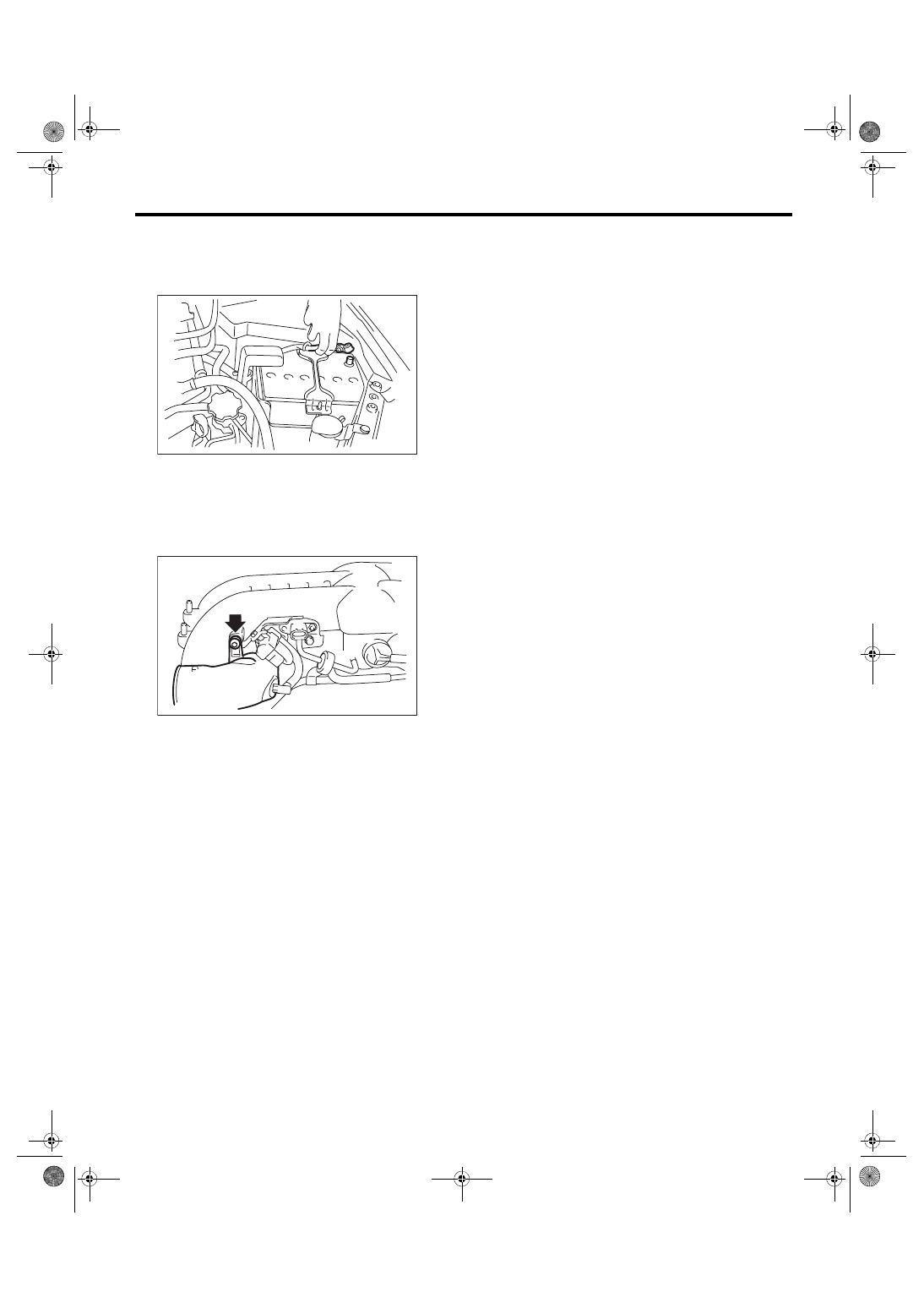
A: REMOVAL
1) Disconnect the ground cable from battery.
2) Remove the intake manifold. <Ref. to FU(w/o
STI)-18, REMOVAL, Intake Manifold.>
3) Remove the sensor, engine harness and fuel
pipe from the intake manifold. <Ref. to FU(w/o
STI)-26, DISASSEMBLY, Intake Manifold.>
4) Remove the intake duct from intake manifold.
B: INSTALLATION
Install in the reverse order of removal.
Tightening torque:
17 N·m (1.7 kgf-m, 12.5 ft-lb)
C: INSPECTION
Check that the intake duct has no deformation,
cracks or other damages.
IN-00203
IN-02505
IN(w/o STI)-12
Intercooler
INTAKE (INDUCTION)
6. Intercooler
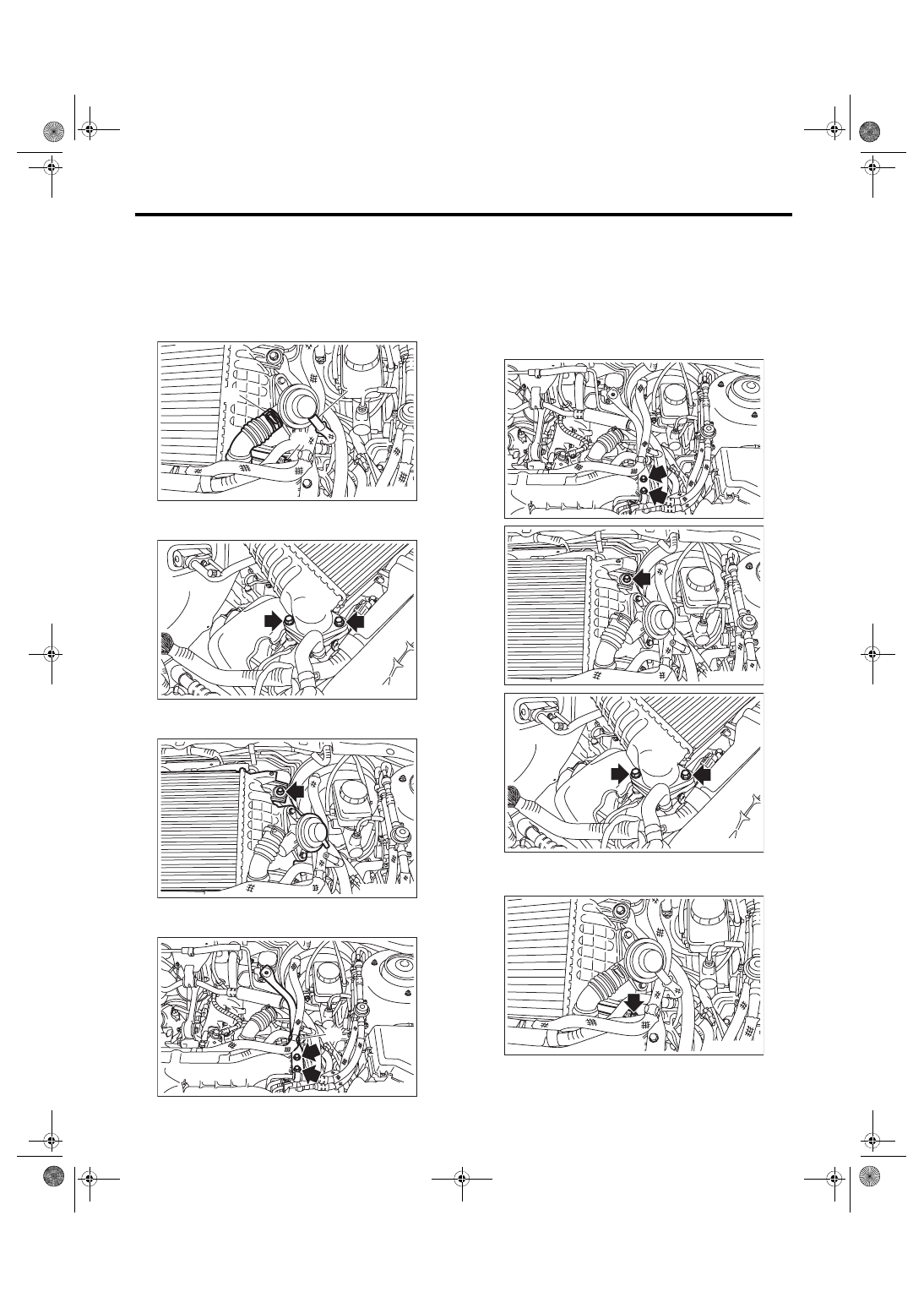
A: REMOVAL
1) Disconnect the air by-pass pipe (A) and vacuum
hose (B) from the air by-pass valve.
2) Loosen the clamp (C) which holds the intake
duct to intercooler.
3) Remove the bolts which secure the intercooler to
the turbocharger.
4) Remove the bolts which secure the intercooler to
the intercooler stay, and remove the intercooler.
5) Remove the brake booster vacuum hose from
the clip (A), and remove the intercooler stay.
B: INSTALLATION
Install in the reverse order of removal.
NOTE:
• Use new O-rings.
• Be careful not to pinch the O-ring.
Tightening torque:
16 N·m (1.6 kgf-m, 11.8 ft-lb)
Tightening torque:
3 N·m (0.3 kgf-m, 2.2 ft-lb)
IN-03069
(C)
(A)
(B)
IN-03070
IN-03071
IN-03072
(A)
IN-03073
IN-03074
IN-03070
IN-03075
IN(w/o STI)-13
Intercooler
INTAKE (INDUCTION)
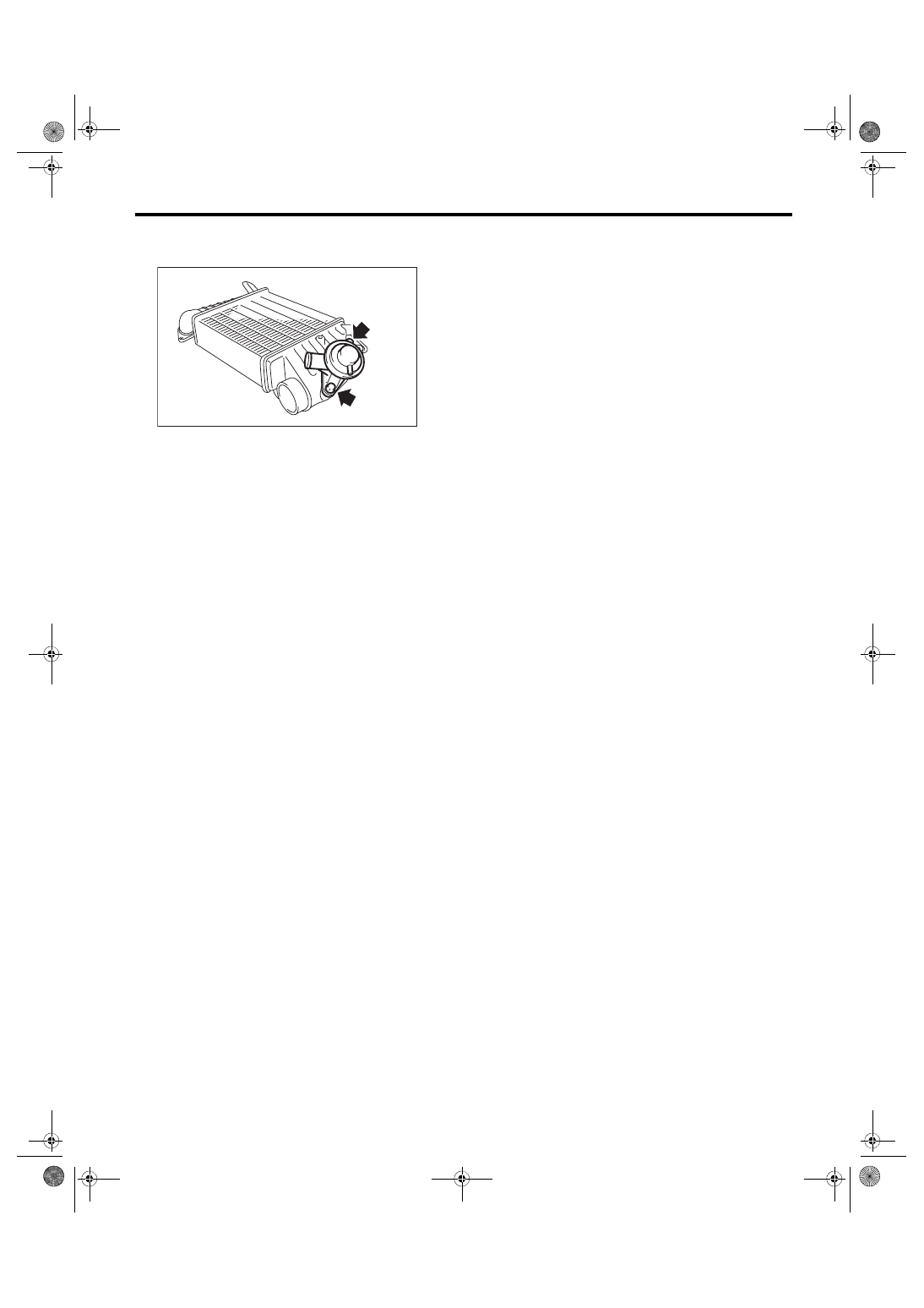
C: DISASSEMBLY
1) Remove the air by-pass valve from intercooler.
D: ASSEMBLY
Assemble in the reverse order of disassembly.
NOTE:
• Use new O-rings.
• Be careful not to pinch the O-ring.
Tightening torque:
6.5 N·m (0.7 kgf-m, 4.8 ft-lb)
E: INSPECTION
1) Check that the intercooler has no deformation,
cracks or other damages.
2) Check that the vacuum hose, air by-pass pipe
and intake duct have no cracks, damage or loose
part.
IN-02094
IN(w/o STI)-14
Turbocharger
INTAKE (INDUCTION)
7. Turbocharger
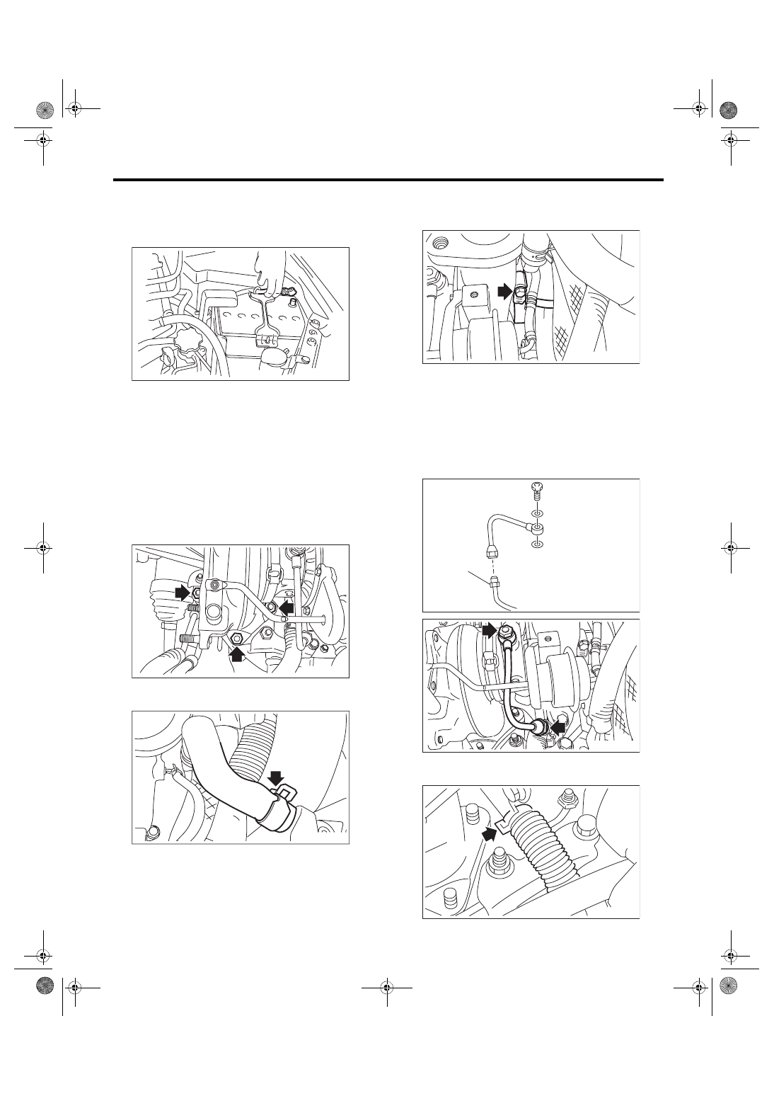
A: REMOVAL
1) Disconnect the ground cable from battery.
2) Lift up the vehicle.
3) Drain approximately 3.0 L (3.2 US qt, 2.6 Imp qt)
of coolant. <Ref. to CO(w/o STI)-13, DRAINING
OF ENGINE COOLANT, REPLACEMENT, Engine
4) Lower the vehicle.
5) Remove the intercooler. <Ref. to IN(w/o STI)-12,
6) Remove the center exhaust pipe. <Ref. to
EX(STI)-8, REMOVAL, Center Exhaust Pipe.>
7) Lower the vehicle.
8) Remove the joint pipe from the turbocharger.
9) Disconnect the engine coolant hoses from cool-
ant filler tank.
10) Disconnect the air control hose (A), and loosen
the clamp holding the intake duct to the turbocharg-
er.
11) Remove the oil inlet pipe from the turbocharg-
er.
CAUTION:
In order to prevent damaging the oil pipe on the
cylinder head side, fix the section (a) shown in
the figure when loosing the oil inlet pipe flare
nut, and avoid the part from rotating together
while loosening the nut.
12) Disconnect the engine coolant hose from the
water pipe.
IN-00203
IN-02935
IN-02936
IN-02940
(A)
(a)
IN-02955
IN-02937
IN-02938
Нет комментариевНе стесняйтесь поделиться с нами вашим ценным мнением.
Текст