Subaru Impreza 3 / Impreza WRX / Impreza WRX STI. Service manual — part 689
ET-15
GPS Antenna
ENTERTAINMENT
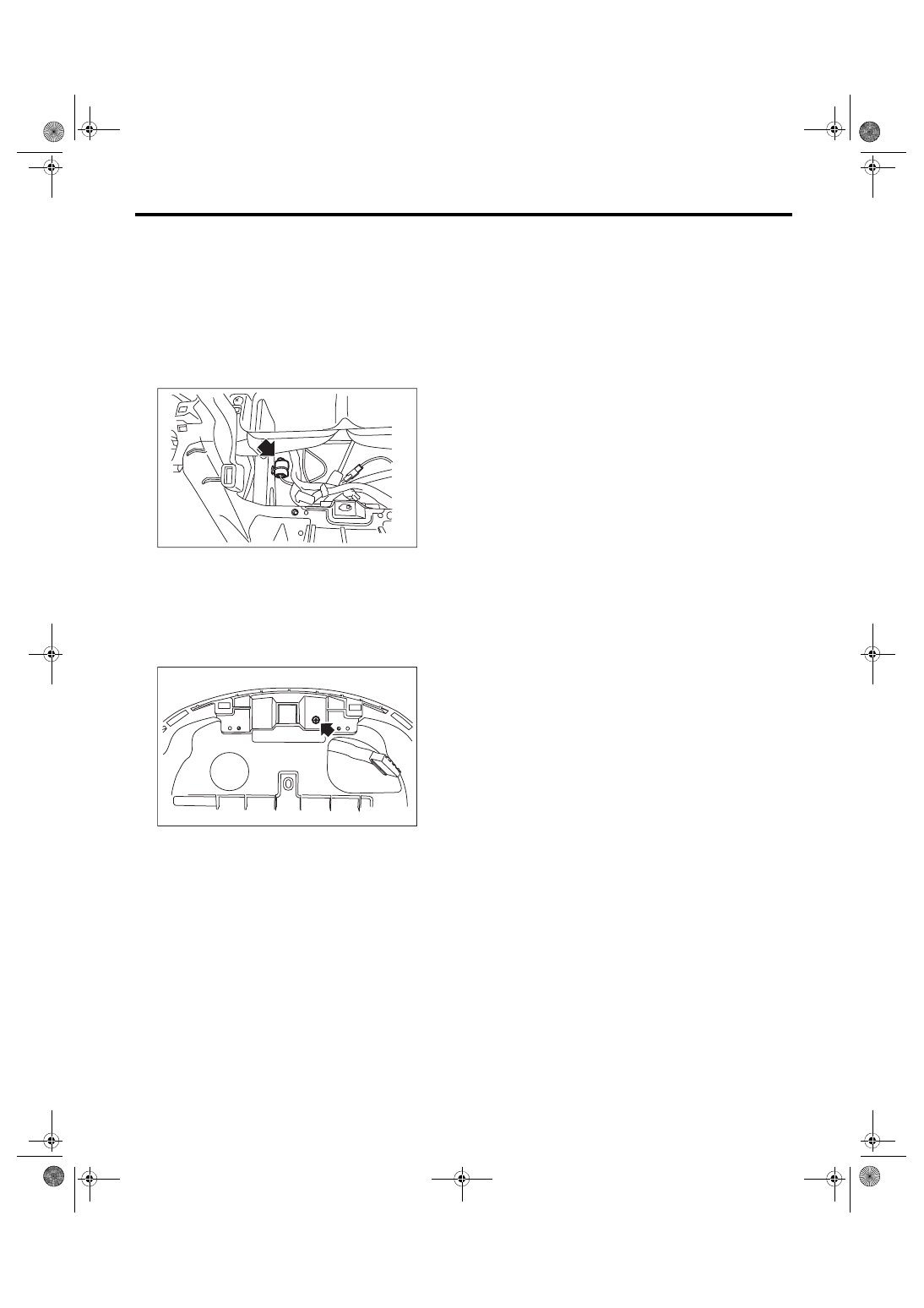
12.GPS Antenna
A: REMOVAL
1) Disconnect the ground cable from the battery.
2) Remove the center panel. <Ref. to EI-52, CEN-
TER PANEL, REMOVAL, Center Console.>
3) Remove the navigation unit. <Ref. to ET-14,
4) Disconnect the connector (green) of GPS anten-
na.
NOTE:
Attach a string of about 50 cm in length, etc. to the
GPS antenna for easy installation work.
5) Remove the combination meter assembly. <Ref.
to IDI-16, REMOVAL, Combination Meter.>
6) Remove the screw and harness clamp to re-
move the GPS antenna.
NOTE:
When the GPS antenna harness connector is
pulled out, remove the string attached to the con-
nector in step 4).
B: INSTALLATION
Install each part in the reverse order of removal.
ET-00296
ET-00297
ET-16
Front Accessory Power Supply Socket
ENTERTAINMENT
13.Front Accessory Power Sup-
ply Socket
A: WIRING DIAGRAM
Refer to “Front Accessory Power Supply Socket
System” in the wiring diagram. <Ref. to WI-121,
WIRING DIAGRAM, Front Accessory Power Sup-
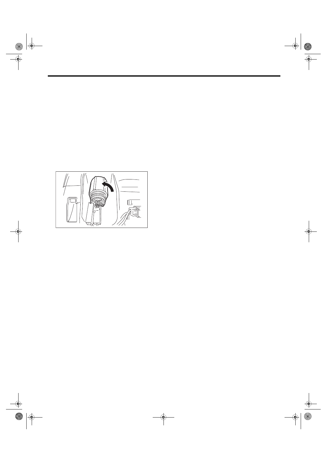
B: REMOVAL
1) Disconnect the ground cable from battery.
2) Remove the instrument panel lower. <Ref. to EI-
54, INSTRUMENT PANEL LOWER, REMOVAL,
3) Disconnect the harness connectors and remove
the front accessory power supply socket.
C: INSTALLATION
Install each part in the reverse order of removal.
ET-00291
ET-17
Rear Accessory Power Supply Socket
ENTERTAINMENT
14.Rear Accessory Power Sup-
ply Socket
A: WIRING DIAGRAM
Refer to “Rear Accessory Power Supply Socket
System” in the wiring diagram. <Ref. to WI-122,
WIRING DIAGRAM, Rear Accessory Power Sup-
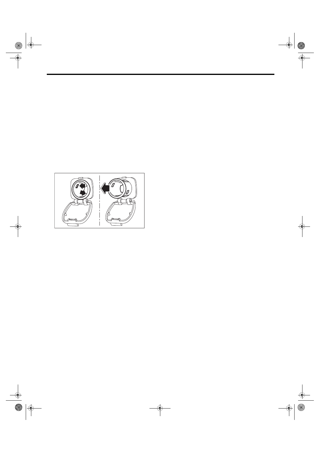
B: REMOVAL
1) Disconnect the ground cable from battery.
2) Remove the console box. <Ref. to EI-51, RE-
3) Disconnect the harness connector, and remove
the claws (two) in accessory power supply socket.
4) Pull the accessory power supply socket out to
remove.
C: INSTALLATION
Install each part in the reverse order of removal.
ET-00377
ET-18
AUX Input Terminal
ENTERTAINMENT
15.AUX Input Terminal
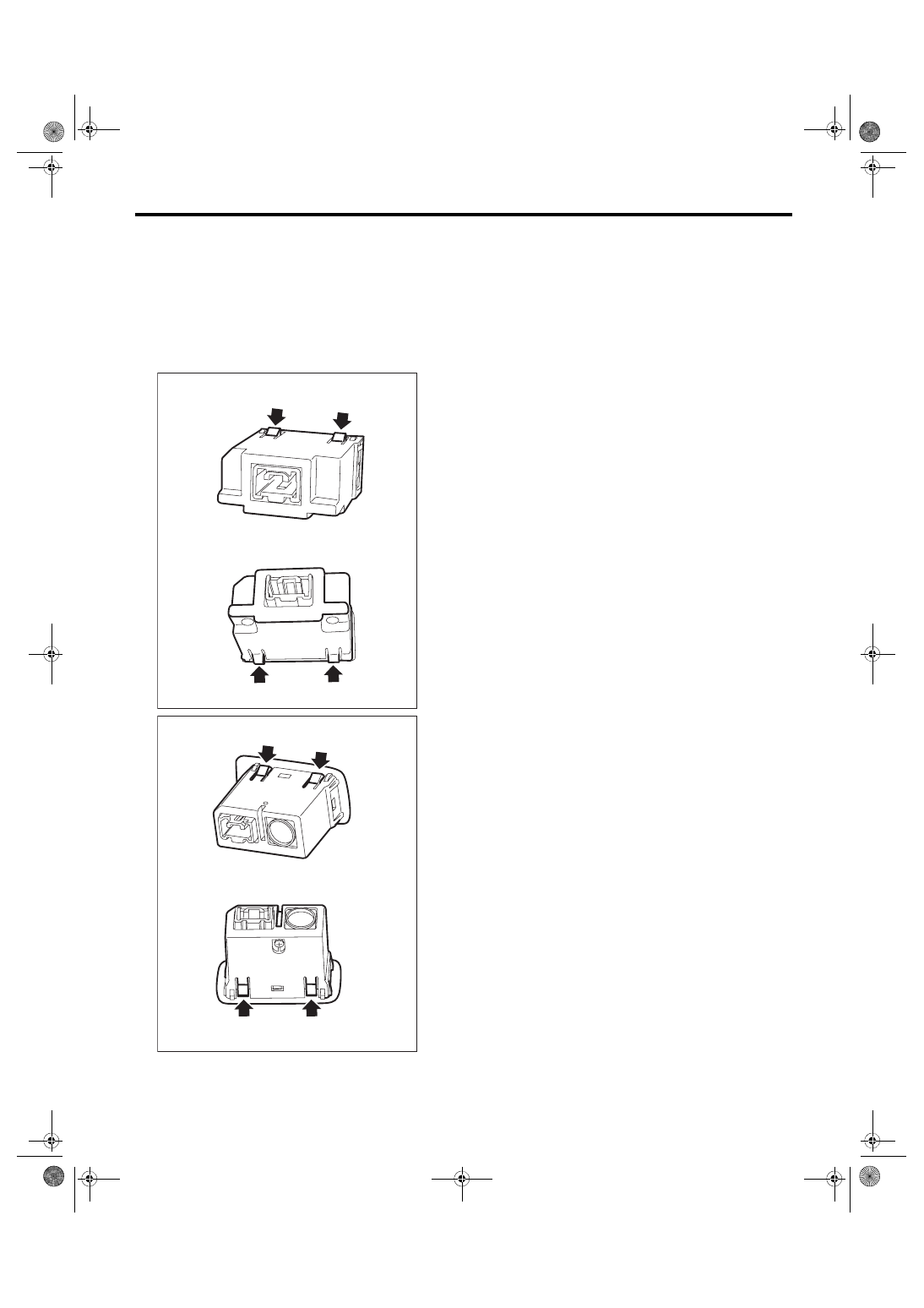
A: REMOVAL
1) Disconnect the ground cable from battery.
2) Remove the console box. <Ref. to EI-51, RE-
3) Disconnect the harness connector.
4) Disengage four claws, and remove the AUX in-
put terminal by pushing it into the console box.
B: INSTALLATION
Install each part in the reverse order of removal.
ET-00477
ET-00476
Нет комментариевНе стесняйтесь поделиться с нами вашим ценным мнением.
Текст