Subaru Impreza 3 / Impreza WRX / Impreza WRX STI. Service manual — part 688
ET-11
Steering Satellite Switch
ENTERTAINMENT
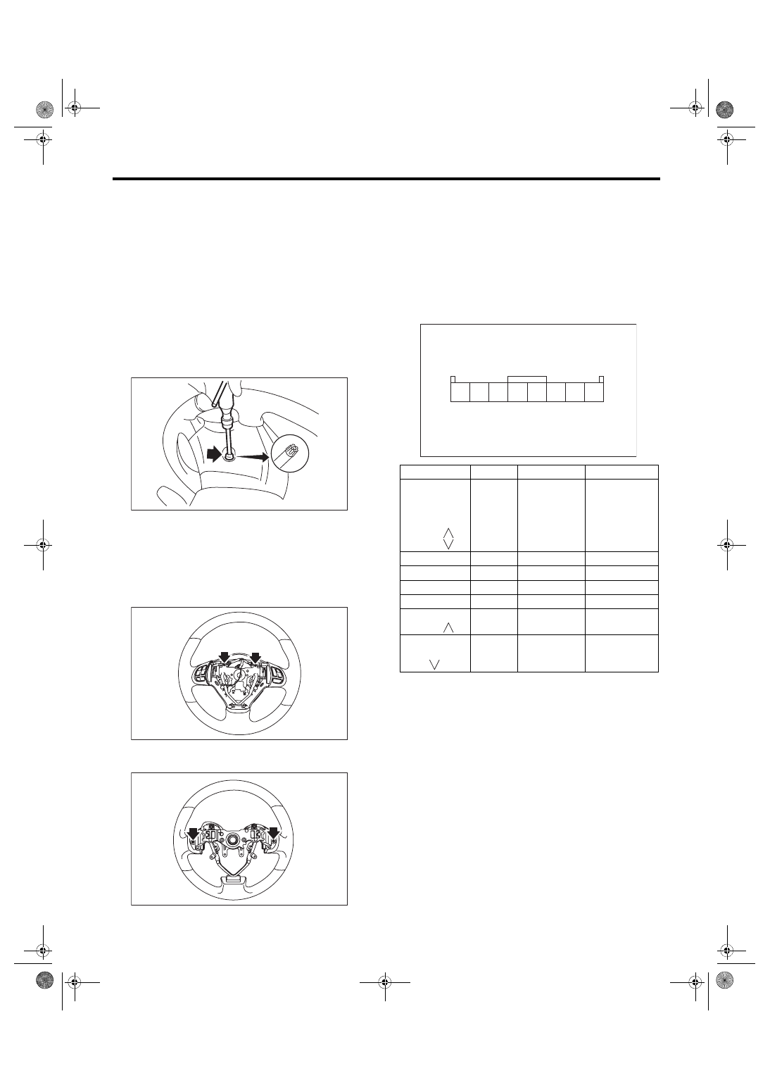
9. Steering Satellite Switch
A: REMOVAL
WARNING:
Before servicing, be sure to read the notes in
the “AB” section for proper handling of the
driver’s airbag module. <Ref. to AB-5, CAU-
1) Set the front wheels in straight ahead position.
2) Turn the ignition switch to OFF.
3) Disconnect the ground cable from battery and
wait for at least 60 seconds before starting work.
4) Using TORX
®
bit T30 (1), loosen two TORX
®
bolts which secure the driver’s airbag module.
5) Disconnect the airbag module connector on
back of the airbag module. <Ref. to AB-8, PROCE-
6) Remove the steering wheel. <Ref. to PS-13, RE-
7) Remove the screws to remove the lower cover
from steering wheel.
8) Loosen the screws on the backside of the steer-
ing wheel and remove the satellite switch.
B: INSTALLATION
Install each part in the reverse order of removal.
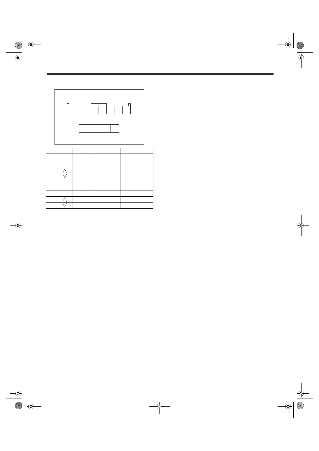
C: INSPECTION
1) Remove the airbag module from the steering
wheel. <Ref. to AB-15, REMOVAL, Driver’s Airbag
2) Check the resistance between satellite switch
connector terminals.
• Model with normal audio and navigation
CC-00018
(1)
CC-00650
CC-00516
Switch
Position
Terminal No.
Standard
Mute
Volume (+)
Volume (–)
Mode
SEEK (
)
SEEK (
)
All OFF
4 and 5
Approx. 4.7 kΩ
Mute
ON
4 and 5
Approx. 22 Ω
Volume (+)
ON
4 and 5
Approx. 90 Ω
Volume (–)
ON
4 and 5
Approx. 200 Ω
Mode
ON
4 and 5
Approx. 360 Ω
Preset CH UP/
SEEK (
)
ON
4 and 5
Approx. 690 Ω
Preset CH
DOWN/SEEK
(
)
ON
4 and 5
Approx. 1.5 kΩ
CC-00487
2 3
1
4 5 6 7 8
ET-12
Steering Satellite Switch
ENTERTAINMENT
• Model with premium audio (Bluetooth applicable)
and model with navigation
3) Replace the satellite switch if the inspection re-
sult is not within the standard value.
Switch
Position
Terminal No.
Standard
Volume (+)
Volume (–)
Mode
SEEK (
)
SEEK (
)
All OFF
4 and 5
5 and 11
Approx. 100 kΩ
Volume (+)
ON
4 and 5
Approx. 1010 Ω
Volume (–)
ON
4 and 5
Approx. 3.21 kΩ
Mode
ON
5 and 11
Less than 1 Ω
SEEK (
)
ON
4 and 5
Less than 1 Ω
SEEK (
)
ON
4 and 5
Approx. 330 Ω
ET-00482
2 3
1
4 5 6 7 8
10 11
9
12 13
ET-13
Steering Switch
ENTERTAINMENT
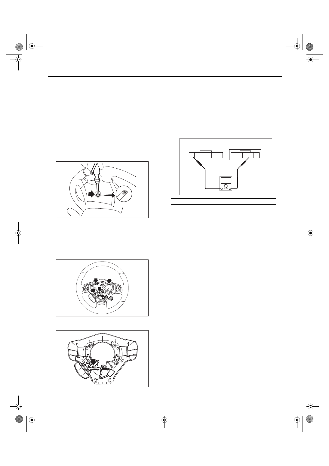
10.Steering Switch
A: REMOVAL
WARNING:
Before servicing, be sure to read the notes in
the “AB” section for proper handling of the
driver’s airbag module. <Ref. to AB-5, CAU-
1) Set the front wheels in straight ahead position.
2) Turn the ignition switch to OFF.
3) Disconnect the ground cable from battery and
wait for at least 60 seconds before starting work.
4) Using TORX
®
bit T30 (1), loosen two TORX
®
bolts which secure the driver’s airbag module.
5) Disconnect the airbag module connector on
back of the airbag module. <Ref. to AB-8, PROCE-
6) Remove the steering wheel.
7) Remove the screws, disconnect the steering
switch connector, and remove the lower cover from
steering wheel.
8) Remove the screws and remove the steering
switch.
B: INSTALLATION
Install each part in the reverse order of removal.
C: INSPECTION
1) Remove the airbag module from the steering
wheel. <Ref. to AB-15, REMOVAL, Driver’s Airbag
2) Connect the tester as shown in the figure, then
check resistance between terminals when each
switch is pressed.
3) If internal resistance is out of specification
shown in the above table, replace the steering
switch.
CC-00018
(1)
ET-00757
ET-00758
Switch
Resistance
No switch pressed
1 MΩ or more
HOOK ON
Approx. 330 Ω
HOOK OFF
Approx. 1010 Ω
TALK
Approx. 3.21 kΩ
3
4
5
1
2
ET-00485
8
7
6
10
9
11
ET-14
Navigation Body
ENTERTAINMENT
11.Navigation Body
A: PROCEDURE
For the removal and installation operation proce-
dures of navigation unit, refer to the removal and in-
Нет комментариевНе стесняйтесь поделиться с нами вашим ценным мнением.
Текст