Subaru Impreza 3 / Impreza WRX / Impreza WRX STI. Service manual — part 714
SL-5
General Description
SECURITY AND LOCKS
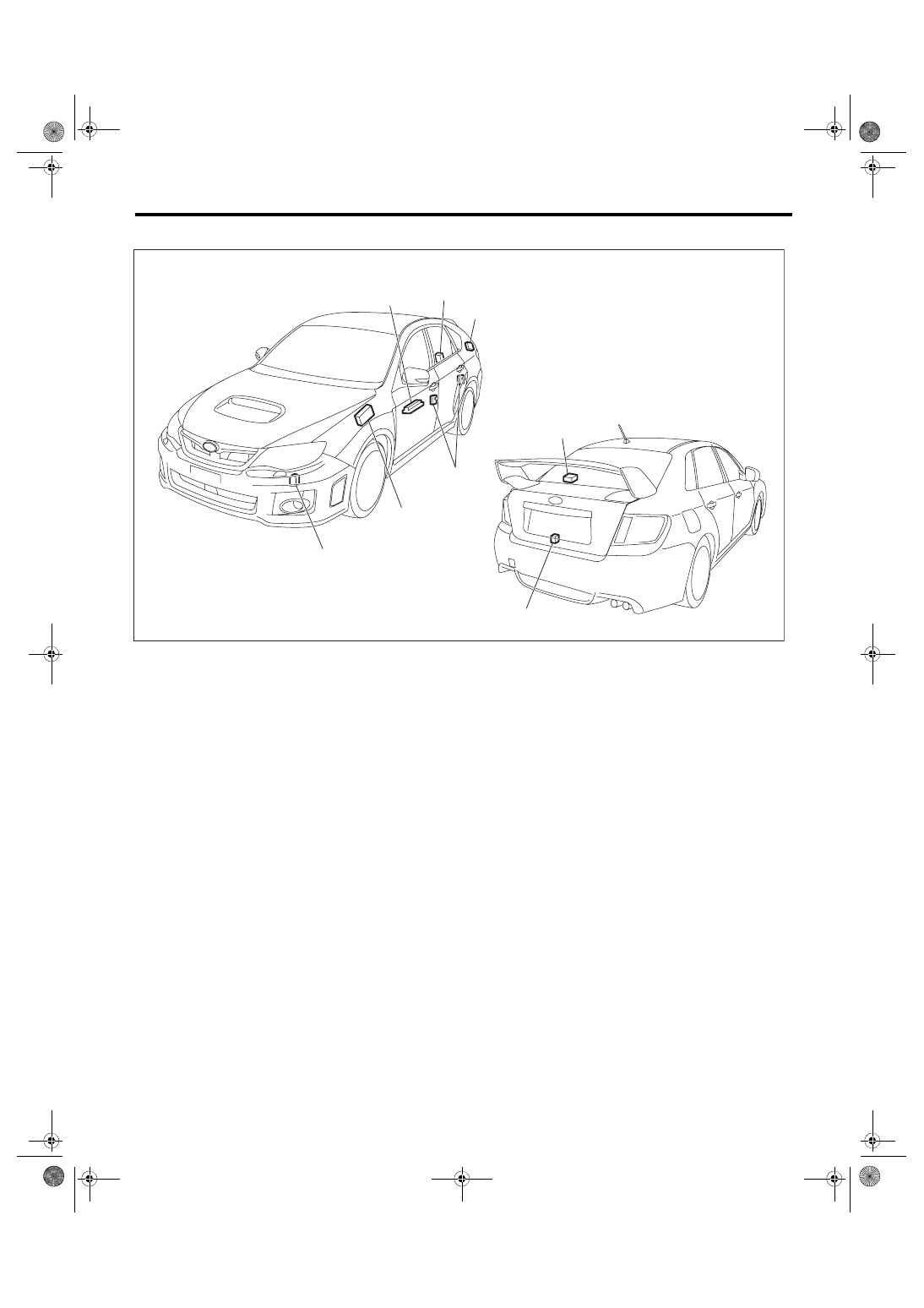
4. KEYLESS ENTRY SYSTEM
(1)
Body integrated unit
(4)
Keyless entry control module
(7)
Trunk lid latch switch (4 door
model)
(2)
Power window main switch
(5)
Door switch
(3)
Rear gate latch switch (5 door
model)
(6)
Keyless buzzer
SL-01356
(1)
(2)
(3)
(4)
(5)
(4)
(7)
(6)
SL-6
General Description
SECURITY AND LOCKS
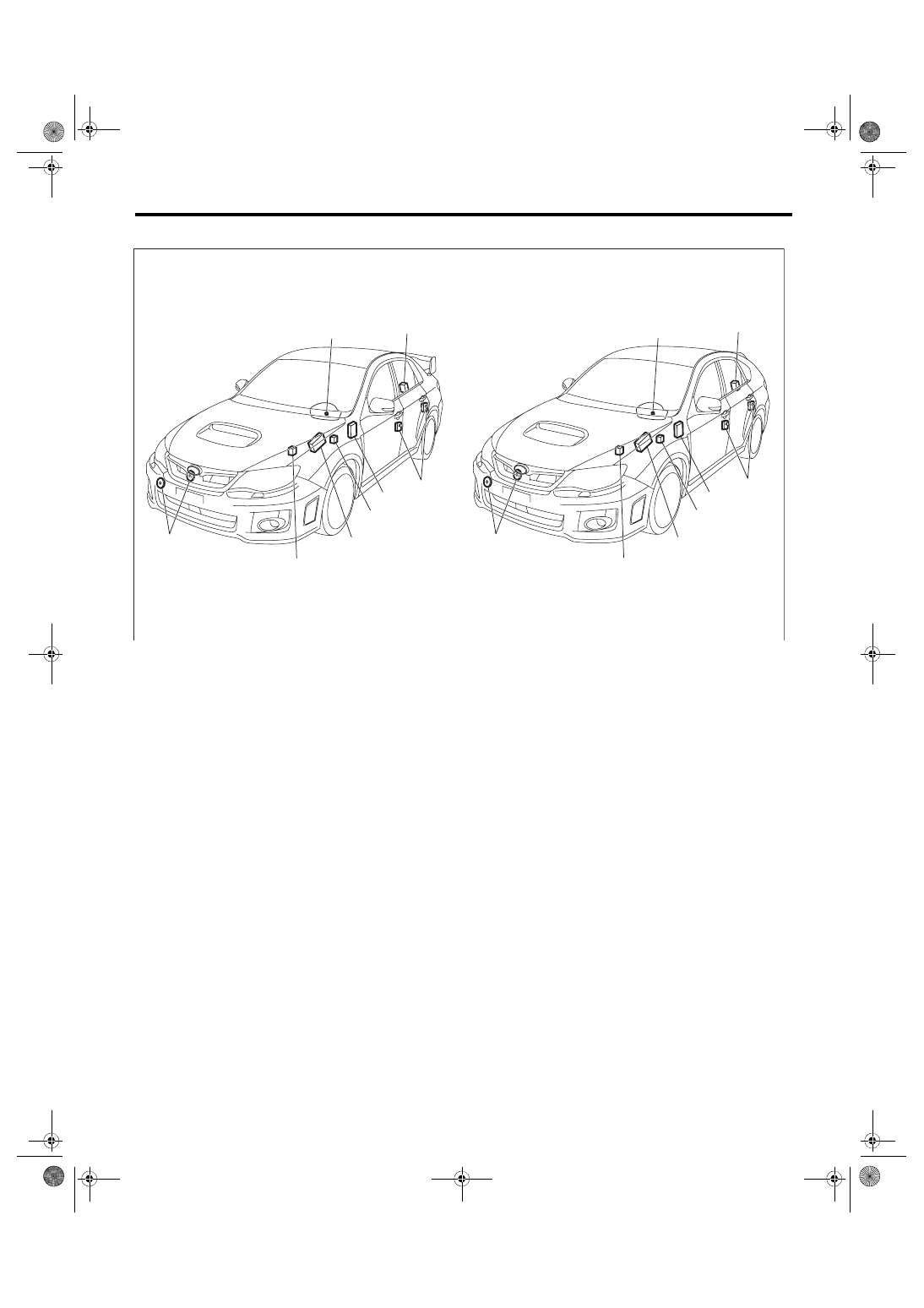
5. SECURITY SYSTEM
B: CAUTION
• Before disassembling or reassembling parts, always disconnect the battery ground cable from battery.
When replacing the audio, control module and other parts provided with memory functions, record the mem-
ory contents before disconnecting the battery ground cable. Otherwise, the memory is cleared.
• When performing a check after disconnecting the battery or restoring from a dead battery condition, per-
form the check after turning the ignition to ON and OFF, then opening and closing the driver’s side door a few
times.
• Reassemble the parts in the reverse order of disassembly procedure unless otherwise indicated.
• Connect the connectors securely during reassembly.
• After reassembly, make sure that the functional parts operate normally.
• If any immobilizer related part has been replaced, make sure to register the immobilizer.
• Do not use any electrical test equipment on the airbag system wiring harnesses and connector circuits.
• Be careful not to damage the airbag system wiring harness when servicing the ignition key cylinder.
(1)
Horn
(4)
Body integrated unit
(7)
Turn signal and hazard module
(2)
Security indicator light (in combi-
nation meter)
(5)
Horn relay (in main fuse box)
(8)
Trunk lid latch switch (4 door
model)
(3)
Impact sensor (driver’s seat instru-
ment panel side) (dealer option)
(6)
Door switch
(9)
Rear gate latch switch (5 door
model)
SL-01357
(1)
(2)
(7)
(4)
(5)
(5)
(1)
(3)
(6)
(6)
(9)
(8)
(2)
(7)
(4)
(3)
SL-7
General Description
SECURITY AND LOCKS
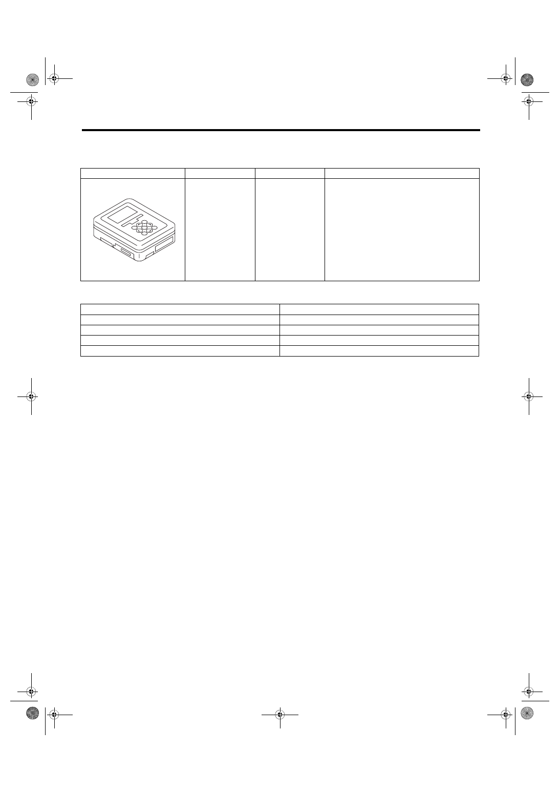
C: PREPARATION TOOL
1. SPECIAL TOOL
2. GENERAL TOOL
ILLUSTRATION
TOOL NUMBER
DESCRIPTION
REMARKS
1B022XU0
SUBARU SELECT
MONITOR III KIT
Used for troubleshooting the electrical system.
TOOL NAME
REMARKS
Circuit tester
Used for measuring resistance and voltage.
Drill
Used for replacing ignition key lock.
TORX
®
T30
Used for removing and installing the door outer handle.
Clip remover
Used for removing trim clip
ST1B022XU0
SL-8
Door Lock Control System
SECURITY AND LOCKS
2. Door Lock Control System
A: WIRING DIAGRAM
B: ELECTRICAL SPECIFICATION
1. BODY INTEGRATED UNIT
Refer to the Control Module I/O Signal of the LAN SYSTEM (DIAGNOSTICS) section. <Ref. to LAN(diag)-
10, ELECTRICAL SPECIFICATION, Control Module I/O Signal.>
C: INSPECTION
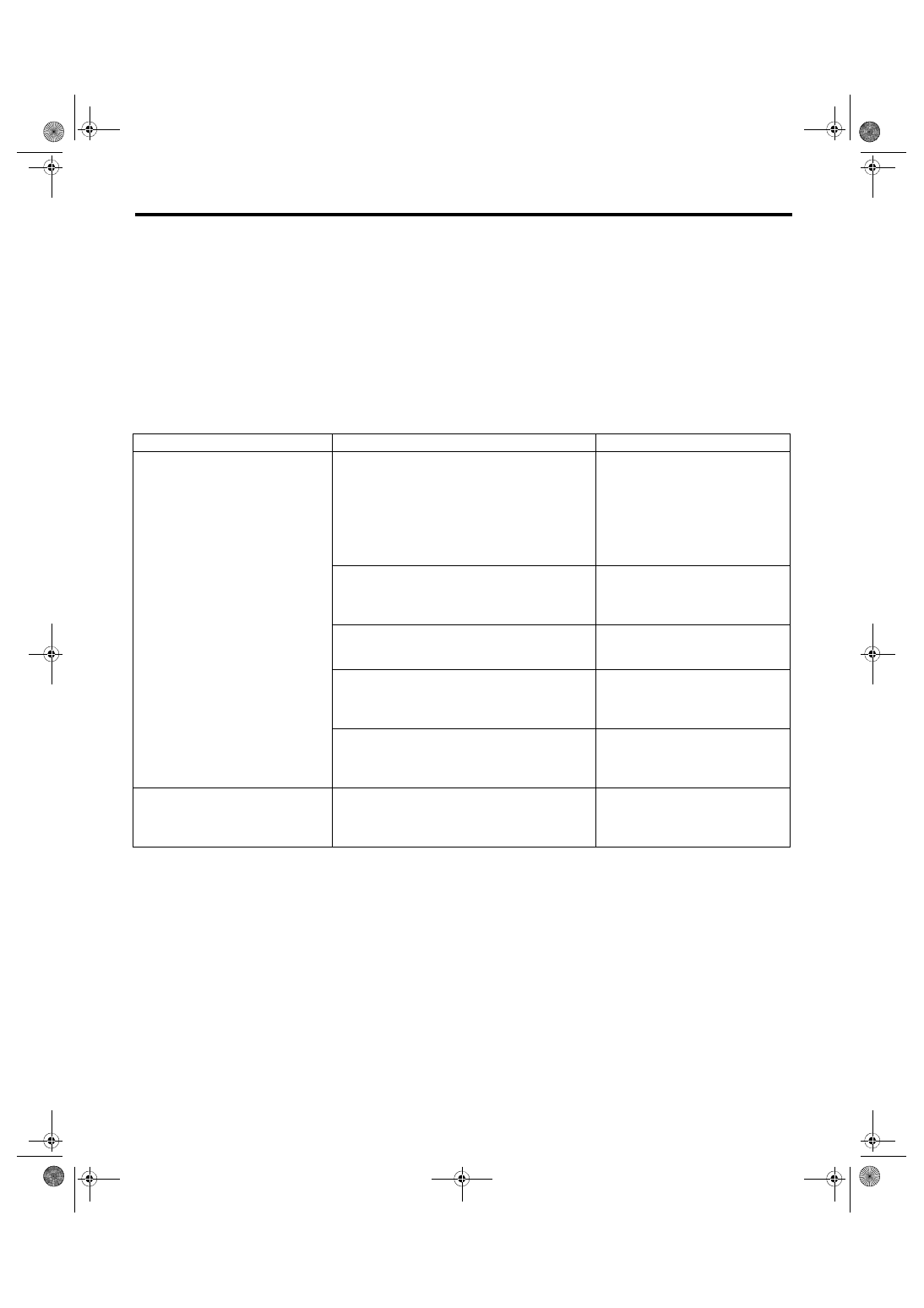
1. SYMPTOM CHART
Symptom
Repair order
Index
The door lock control system does
not operate.
1. Remove and visually inspect the following
fuses.
• No. 3 (in fuse & relay box)
• No. 7 (in fuse & relay box)
• No. 8 (in main fuse box)
If the fuse is blown out, replace the
fuse with a new part.
When there is no defective with the
fuse, check the power supply and
ground circuit. <Ref. to SL-9,
CHECK POWER SUPPLY AND
GROUND CIRCUIT, INSPECTION,
Door Lock Control System.>
2. Check the power supply and ground circuit for
body integrated unit.
<Ref. to SL-9, CHECK POWER
SUPPLY AND GROUND CIRCUIT,
INSPECTION, Door Lock Control
System.>
3. Check the door lock switch and the circuit.
<Ref. to SL-9, CHECK DOOR LOCK
SWITCH, INSPECTION, Door Lock
Control System.>
4. Check the rear gate opener button and the cir-
cuit.
<Ref. to SL-10, CHECK REAR
GATE OPENER BUTTON CIRCUIT,
INSPECTION, Door Lock Control
System.>
5. Check the door lock actuator and the circuit.
<Ref. to SL-11, CHECK DOOR
LOCK ACTUATOR AND CIRCUIT,
INSPECTION, Door Lock Control
System.>
A specific door lock actuator does not
operate.
Check the door lock actuator and circuit.
<Ref. to SL-11, CHECK DOOR
LOCK ACTUATOR AND CIRCUIT,
INSPECTION, Door Lock Control
System.>
Нет комментариевНе стесняйтесь поделиться с нами вашим ценным мнением.
Текст