Subaru Impreza 3 / Impreza WRX / Impreza WRX STI. Service manual — part 315
GD(H4DOTC)-12
Diagnostic Trouble Code (DTC) Detecting Criteria
GENERAL DESCRIPTION
E: DTC B1575 INCORRECT IMMOBILIZER KEY
1. OUTLINE OF DIAGNOSIS
NOTE:
For the detection standard, refer to DTC B1570. <Ref. to GD(H4DOTC)-11, DTC B1570 ANTENNA, Diag-
nostic Trouble Code (DTC) Detecting Criteria.>
F: DTC B1576 EGI CONTROL MODULE EEPROM
1. OUTLINE OF DIAGNOSIS
NOTE:
For the detection standard, refer to DTC B1570. <Ref. to GD(H4DOTC)-11, DTC B1570 ANTENNA, Diag-
nostic Trouble Code (DTC) Detecting Criteria.>
G: DTC B1577 IMM CONTROL MODULE EEPROM
1. OUTLINE OF DIAGNOSIS
NOTE:
For the detection standard, refer to DTC B1570. <Ref. to GD(H4DOTC)-11, DTC B1570 ANTENNA, Diag-
nostic Trouble Code (DTC) Detecting Criteria.>
H: DTC B1578 METER FAILURE
1. OUTLINE OF DIAGNOSIS
NOTE:
For the detection standard, refer to DTC B1570. <Ref. to GD(H4DOTC)-11, DTC B1570 ANTENNA, Diag-
GD(H4DOTC)-13
Diagnostic Trouble Code (DTC) Detecting Criteria
GENERAL DESCRIPTION
I: DTC P0011 INTAKE CAMSHAFT POSITION - TIMING OVER-ADVANCED OR
SYSTEM PERFORMANCE (BANK 1)
1. OUTLINE OF DIAGNOSIS
Detect the AVCS system malfunction.
Judge NG when the amount of AVCS actual timing advance does not approach to the amount of AVCS target
timing advance.
2. COMPONENT DESCRIPTION
3. ENABLE CONDITIONS
4. GENERAL DRIVING CYCLE
Perform the diagnosis continuously after warming up when the engine speed increases and AVCS operates.
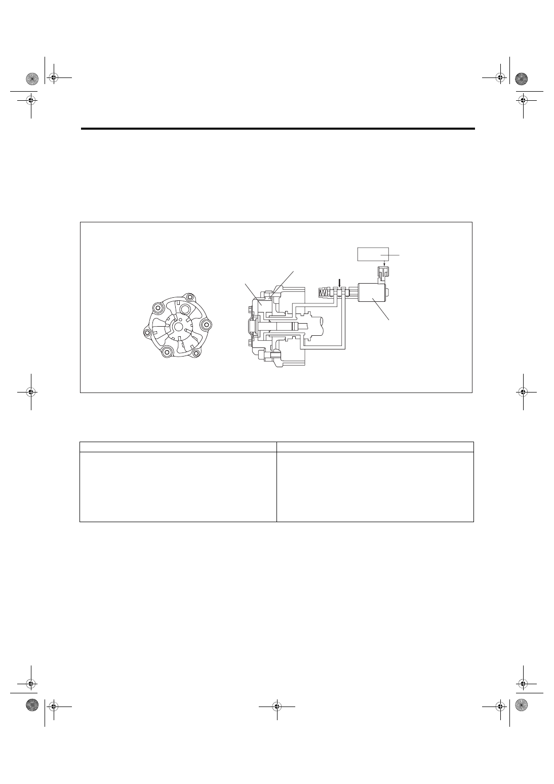
(1)
AVCS timing controller
(3)
Engine control module (ECM)
(5)
Oil pressure
(2)
Vane
(4)
Oil flow control solenoid valve
Secondary Parameters
Enable Conditions
Time of establishing all secondary parameter conditions
≥ 3000 ms
Battery voltage
≥ 10.9 V
Engine speed
≥ 1300 rpm (models without SI-DRIVE)
≥ 1500 rpm (models with SI-DRIVE)
Engine coolant temperature
≥ 60 °C (140 °F)
AVCS control
Operation
Target timing advance change amount (per 64 ms)
< 1.07 °CA
EN-01852
(3)
(4)
(1)
(5)
(2)

GD(H4DOTC)-14
Diagnostic Trouble Code (DTC) Detecting Criteria
GENERAL DESCRIPTION
5. DIAGNOSTIC METHOD
1) When the conditions during which the differences of AVCS target timing advance amount and AVCS ac-
tual timing advance amount is large continues for certain amount of time.
2) When the differences of target timing advance amount and actual timing advance amount is calculated
during AVCS control, and the difference per predetermined time is the specified value or larger.
• Abnormality Judgment
Judge as NG when the following conditions are established within the predetermined time.
Judgment Value
Time Needed for Diagnosis: 20000 ms
Time Needed for Diagnosis: 30000 ms
Malfunction Indicator Light Illumination: Illuminates when malfunction occurs in 2 continuous driving cy-
cles.
• Normality Judgment
Judge as OK and clear the NG if the following conditions are established within the predetermined time.
Judgment Value
Time Needed for Diagnosis: 20000 ms
Time Needed for Diagnosis: 30000 ms
Models without SI-DRIVE
Malfunction Criteria
Threshold Value
Σ(Target position – Actual position)
> 5300 °CA (Bank 1)
> 5300 °CA (Bank 2)
or
Σ(Target position – Actual position)
< –5300 °CA (Bank 1)
< –5300 °CA (Bank 2)
Models with SI-DRIVE
Malfunction Criteria
Threshold Value
Σ(Target position – Actual position)
> 8000 °CA (Bank 1)
> 8000 °CA (Bank 2)
or
Σ(Target position – Actual position)
< –8000 °CA (Bank 1)
< –8000 °CA (Bank 2)
Models without SI-DRIVE
Malfunction Criteria
Threshold Value
Σ(Target position – Actual position)
≤ 5300 °CA (Bank 1)
≤ 5300 °CA (Bank 2)
and
≥ –5300 °CA (Bank 1)
≥ –5300 °CA (Bank 2)
Models with SI-DRIVE
Malfunction Criteria
Threshold Value
Σ(Target position – Actual position)
≤ 8000 °CA (Bank 1)
≤ 8000 °CA (Bank 2)
and
≥ –8000 °CA (Bank 1)
≥ –8000 °CA (Bank 2)
GD(H4DOTC)-15
Diagnostic Trouble Code (DTC) Detecting Criteria
GENERAL DESCRIPTION
J: DTC P0014 EXHAUST AVCS SYSTEM 1 (RANGE/PERFORMANCE)
1. OUTLINE OF DIAGNOSIS
Detect the exhaust AVCS system malfunction.
Judge NG when the amount of exhaust AVCS actual timing advance does not approach the amount of ex-
haust AVCS target timing advance.
2. COMPONENT DESCRIPTION
3. ENABLE CONDITIONS
4. GENERAL DRIVING CYCLE
Perform the diagnosis continuously after warming up when the engine speed increases and exhaust AVCS
operates.
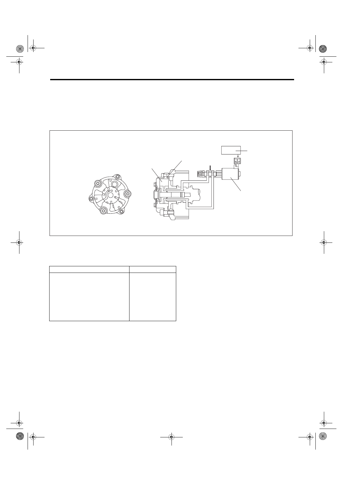
(1)
Exhaust AVCS timing controller
(3)
Engine control module (ECM)
(5)
Oil pressure
(2)
Vane
(4)
Oil flow control solenoid valve
Secondary Parameters
Enable Conditions
Time of establishing all secondary
parameter conditions
≥ 3000 ms
Battery voltage
≥ 10.9 V
Engine speed
≥ 1500 rpm
Engine coolant temperature
≥ 60 °C (140 °F)
Exhaust AVCS control
Operation
Target timing advance change amount
(per 64 ms)
< 1.07 °CA
EN-01852
(3)
(4)
(1)
(5)
(2)
Нет комментариевНе стесняйтесь поделиться с нами вашим ценным мнением.
Текст