Subaru Impreza 3 / Impreza WRX / Impreza WRX STI. Service manual — part 314
GD(H4DOTC)-8
List of Diagnostic Trouble Code (DTC)
GENERAL DESCRIPTION
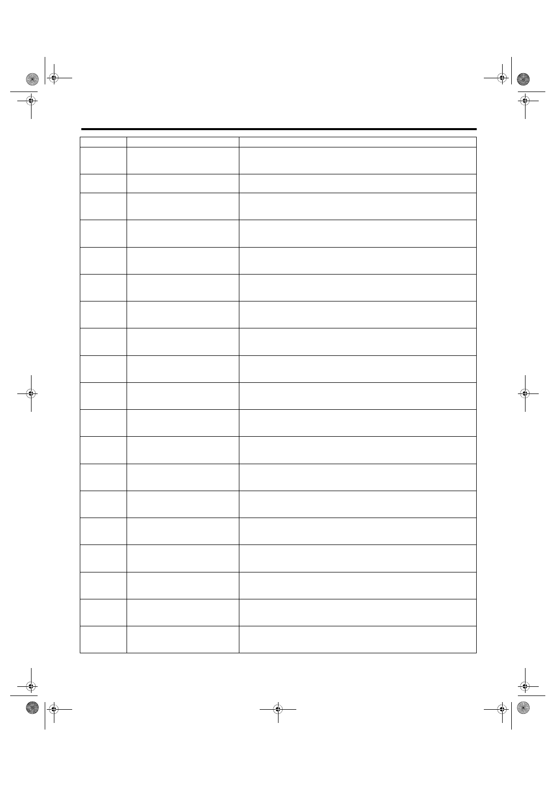
P1449
Evaporative Emission Cont. Sys.
Air Filter Clog
P1451
Evaporative Emission Cont. Sys.
P2004
Intake Manifold Runner Control
Stuck Open (Bank 1)
P2005
Intake Manifold Runner Control
Stuck Open (Bank 2)
P2006
Intake Manifold Runner Control
Stuck Closed (Bank 1)
P2007
Intake Manifold Runner Control
Stuck Closed (Bank 2)
P2008
Intake Manifold Runner Control
Circuit / Open (Bank 1)
P2009
Intake Manifold Runner Control
Circuit Low (Bank 1)
P2011
Intake Manifold Runner Control
Circuit / Open (Bank 2)
P2012
Intake Manifold Runner Control
Circuit Low (Bank 2)
P2016
Tumble Generated Valve Position
Sensor 1 Circuit Low
P2017
Intake Manifold Runner Position
Sensor / Switch Circuit High (Bank
1)
P2021
Tumble Generated Valve Position
Sensor 2 Circuit Low
P2022
Intake Manifold Runner Position
Sensor / Switch Circuit High (Bank
2)
P2088
Intake Camshaft Position Actuator
Control Circuit Low (Bank 1)
P2089
Intake Camshaft Position Actuator
Control Circuit High (Bank 1)
P2090
Exhaust Camshaft Position Actua-
tor Control Circuit Low (Bank 1)
P2091
Exhaust Camshaft Position Actua-
tor Control Circuit High (Bank 1)
P2092
Intake Camshaft Position Actuator
Control Circuit Low (Bank 2)
DTC
Item
Note
GD(H4DOTC)-9
List of Diagnostic Trouble Code (DTC)
GENERAL DESCRIPTION
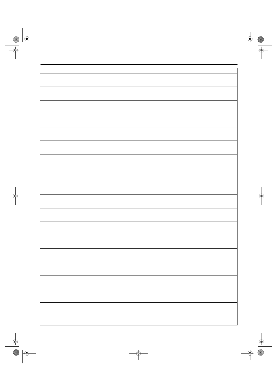
P2093
Intake Camshaft Position Actuator
Control Circuit High (Bank 2)
P2094
Exhaust Camshaft Position Actua-
tor Control Circuit Low (Bank 2)
P2095
Exhaust Camshaft Position Actua-
tor Control Circuit High (Bank 2)
P2096
Post Catalyst Fuel Trim System
Too Lean (Bank 1)
P2097
Post Catalyst Fuel Trim System
Too Rich (Bank 1)
P2101
Throttle Actuator Control Motor Cir-
cuit Range/Performance
P2102
Throttle Actuator Control Motor Cir-
cuit Low
P2103
Throttle Actuator Control Motor Cir-
cuit High
P2109
Throttle/Pedal Position Sensor “A”
Minimum Stop Performance
P2119
Throttle Actuator Control Throttle
Body Range/Performance
P2122
Throttle/Pedal Position Sensor/
Switch “D” Circuit Low Input
P2123
Throttle/Pedal Position Sensor/
Switch “D” Circuit High Input
P2127
Throttle/Pedal Position Sensor/
Switch “E” Circuit Low Input
P2128
Throttle/Pedal Position Sensor/
Switch “E” Circuit High Input
P2135
Throttle/Pedal Position Sensor/
Switch “A”/“B” Voltage Correlation
P2138
Throttle/Pedal Position Sensor/
Switch “D”/“E” Voltage Correlation
P2195
O2 Sensor Signal Biased/Stuck
Lean (Bank 1 Sensor 1)
P2196
O2 Sensor Signal Biased/Stuck
Rich (Bank 1 Sensor 1)
P219A
Bank 1 Air-Fuel Ratio Imbalance
DTC
Item
Note
GD(H4DOTC)-10
List of Diagnostic Trouble Code (DTC)
GENERAL DESCRIPTION
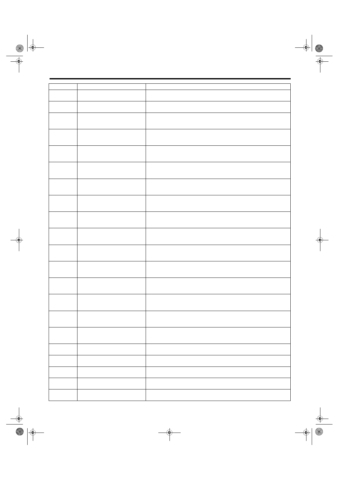
P2257
Air System Control "A" Circuit Low
P2258
Air System Control "A" Circuit High <Ref. to GD(H4DOTC)-275, DTC P2258 AIR SYSTEM CONTROL "A" CIR-
CUIT HIGH, Diagnostic Trouble Code (DTC) Detecting Criteria.>
P2401
Evaporative Emission System
Leak Detection Pump Control Cir-
cuit Low
P2402
Evaporative Emission System
Leak Detection Pump Control Cir-
cuit High
P2404
Evaporative Emission System
Leak Detection Pump Sense Cir-
cuit Range/Performance
P2419
Evaporative Emission System
Switching Valve Control Circuit
Low
P2420
Evaporative Emission System
Switching Valve Control Circuit
High
P2431
Secondary Air Injection System Air
Flow /Pressure Sensor Circuit
Range/Performance
P2432
Secondary Air Injection System Air
Flow /Pressure Sensor Circuit Low
P2433
Secondary Air Injection System Air
Flow /Pressure Sensor Circuit High
P2440
Secondary Air Injection System
Switching Valve Stuck Open
(Bank1)
P2441
Secondary Air Injection System
Switching Valve Stuck Closed
(Bank1)
P2442
Secondary Air Injection System
Switching Valve Stuck Open
(Bank2)
P2443
Secondary Air Injection System
Switching Valve Stuck Closed
(Bank2)
P2444
Secondary Air Injection System
Pump Stuck On
P2610
ECM/PCM Internal Engine Off
Timer Performance
U0073
CAN Failure, Bus ‘Off’ Detection
U0122
CAN (VDC) Data Not Loaded
U0140
CAN (BCU) Data Not Loaded
U0416
CAN (VDC) Data Abnormal
U0422
CAN (BCU) Data Abnormal
DTC
Item
Note
GD(H4DOTC)-11
Diagnostic Trouble Code (DTC) Detecting Criteria
GENERAL DESCRIPTION
2. Diagnostic Trouble Code (DTC) Detecting Criteria
A: DTC B1570 ANTENNA
1. OUTLINE OF DIAGNOSIS
2. ENABLE CONDITIONS
When starting the engine.
3. GENERAL DRIVING CYCLE
Perform the diagnosis only after starting the engine.
4. DIAGNOSTIC METHOD
Judge as NG when the conditions for the outline of the diagnosis of the top are established.
B: DTC B1571 REFERENCE CODE INCOMPATIBILITY
1. OUTLINE OF DIAGNOSIS
NOTE:
For the detection standard, refer to DTC B1570. <Ref. to GD(H4DOTC)-11, DTC B1570 ANTENNA, Diag-
nostic Trouble Code (DTC) Detecting Criteria.>
C: DTC B1572 IMM CIRCUIT FAILURE (EXCEPT ANTENNA CIRCUIT)
1. OUTLINE OF DIAGNOSIS
NOTE:
For the detection standard, refer to DTC B1570. <Ref. to GD(H4DOTC)-11, DTC B1570 ANTENNA, Diag-
nostic Trouble Code (DTC) Detecting Criteria.>
D: DTC B1574 KEY COMMUNICATION FAILURE
1. OUTLINE OF DIAGNOSIS
NOTE:
For the detection standard, refer to DTC B1570. <Ref. to GD(H4DOTC)-11, DTC B1570 ANTENNA, Diag-
nostic Trouble Code (DTC) Detecting Criteria.>
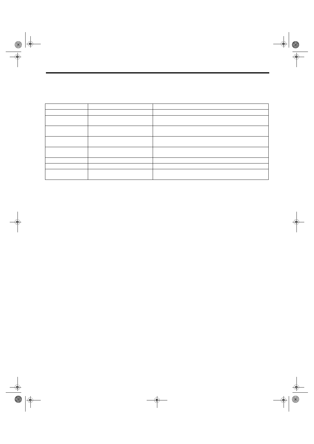
DTC
Item
OUTLINE OF DIAGNOSIS
B1570
Antenna
Faulty antenna
B1571
Reference Code Incompatibility
Reference code incompatibility between body integrated unit and
ECM
B1572
IMM Circuit Failure (Except
Antenna Circuit)
Communication failure between body integrated unit and ECM
B1574
Key Communication Failure
The body integrated unit to confirm the key (transponder) ID code
has malfunction, of the transponder is faulty.
B1575
Incorrect Immobilizer Key
Incorrect immobilizer key (Use of unregistered key in body inte-
grated unit)
B1576
EGI Control Module EEPROM
ECM malfunctioning
B1577
IMM Control Module EEPROM
Body integrated unit malfunctioning
B1578
Meter Failure
Reference code incompatibility between combination meter and
body integrated unit
Нет комментариевНе стесняйтесь поделиться с нами вашим ценным мнением.
Текст