Subaru Impreza 3 / Impreza WRX / Impreza WRX STI. Service manual — part 546
VDC(diag)-83
Diagnostic Procedure with Diagnostic Trouble Code (DTC)
VEHICLE DYNAMICS CONTROL (VDC) (DIAGNOSTICS)
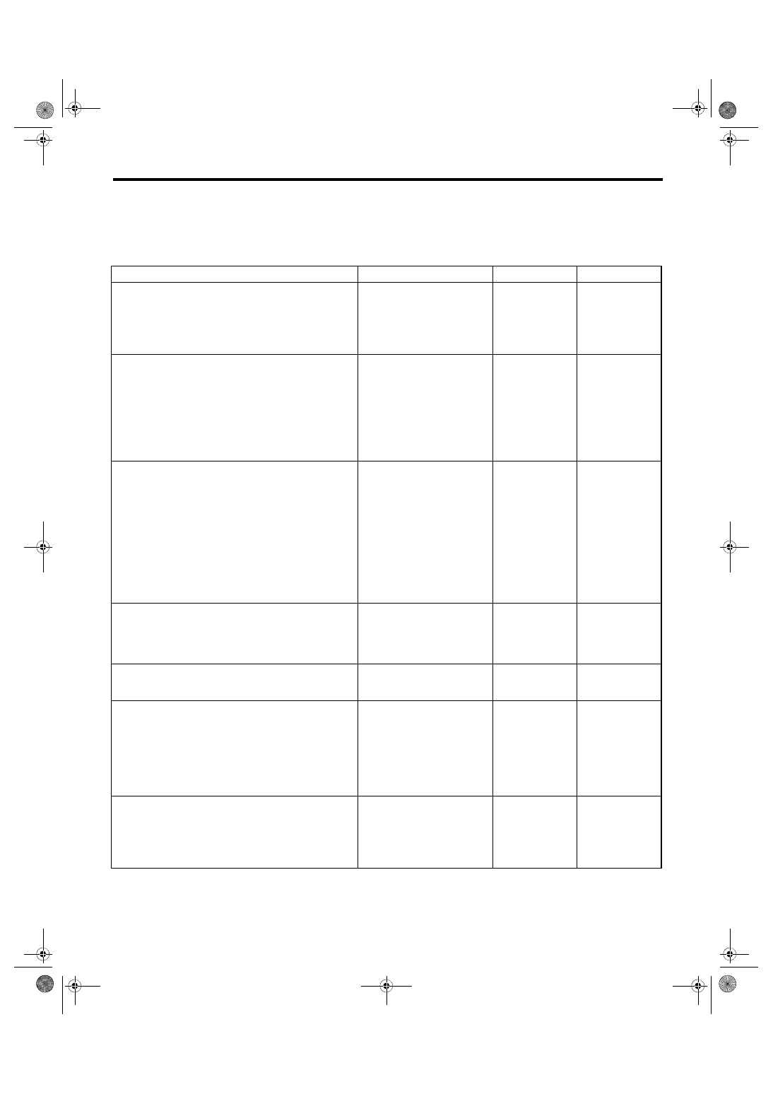
AI: DTC C0056 G SENSOR SIGNAL
DTC DETECTING CONDITION:
Defective longitudinal G sensor output signal
TROUBLE SYMPTOM:
Hill start assist does not operate.
Step
Check
Yes
No
1
WHETHER A WHEEL TURNED FREELY OR
NOT.
Check if the wheels have been turned freely for
one minute or more, such as when the vehicle is
jacked-up, under full-lock cornering or when the
wheels are not in contact with road surface.
Did the wheels turn freely?
VDC is normal.
Clear the memory.
2
CHECK OUTPUT OF LONGITUDINAL G
SENSOR USING SUBARU SELECT MONI-
TOR.
1) Park the vehicle on a level surface.
2) Select “Current Data Display & Save” on the
Subaru Select Monitor. <Ref. to VDC(diag)-19,
READ CURRENT DATA, OPERATION, Subaru
Select Monitor.>
3) Read the «Fr Rr G sensor Output».
Is the indicated reading on the
monitor display –1.2 — 1.2 m/s
2
?
Replace the yaw
rate & G sensor.
<Ref. to VDC-20,
Yaw Rate and G
Sensor.>
3
CHECK OUTPUT OF LONGITUDINAL G
SENSOR USING SUBARU SELECT MONI-
TOR.
1) Turn the ignition switch to OFF.
2) Remove the yaw rate & G sensor from vehi-
cle. <Ref. to VDC-20, Yaw Rate and G Sensor.>
3) Turn the ignition switch to ON, and select the
“Current Data Display & Save” in Subaru Select
Monitor. <Ref. to VDC(diag)-19, READ CUR-
RENT DATA, OPERATION, Subaru Select
Monitor.>
4) Read the «Fr Rr G sensor Output».
When the yaw rate & G sensor is
inclined 90° to the front, is the
indicated value 6.8 — 12.8 m/s
2
?
Replace the yaw
rate & G sensor.
<Ref. to VDC-20,
Yaw Rate and G
Sensor.>
4
CHECK OUTPUT OF LONGITUDINAL G
SENSOR USING SUBARU SELECT MONI-
TOR.
Read the «Fr Rr G sensor Output».
When the yaw rate & G sensor
is inclined 90° to the rear, is the
indicated value –6.8 — –12.8
m/s
2
?
Replace the yaw
rate & G sensor.
<Ref. to VDC-20,
Yaw Rate and G
Sensor.>
5
CHECK POOR CONTACT OF CONNECTOR.
Turn the ignition switch to OFF.
Is there poor contact of connec-
tor between VDCCM&H/U and
yaw rate & G sensor?
Repair the connec-
tor.
6
CHECK VDCCM&H/U.
1) Connect all connectors.
2) Clear the memory. <Ref. to VDC(diag)-27,
Clear Memory Mode.>
3) Perform the Inspection Mode. <Ref. to
VDC(diag)-26, Inspection Mode.>
4) Read the DTC.
Is the same DTC displayed?
7
CHECK OTHER DTC DETECTION.
Is any other DTC displayed?
Temporary poor
contact occurs.
VDC(diag)-84
Diagnostic Procedure with Diagnostic Trouble Code (DTC)
VEHICLE DYNAMICS CONTROL (VDC) (DIAGNOSTICS)
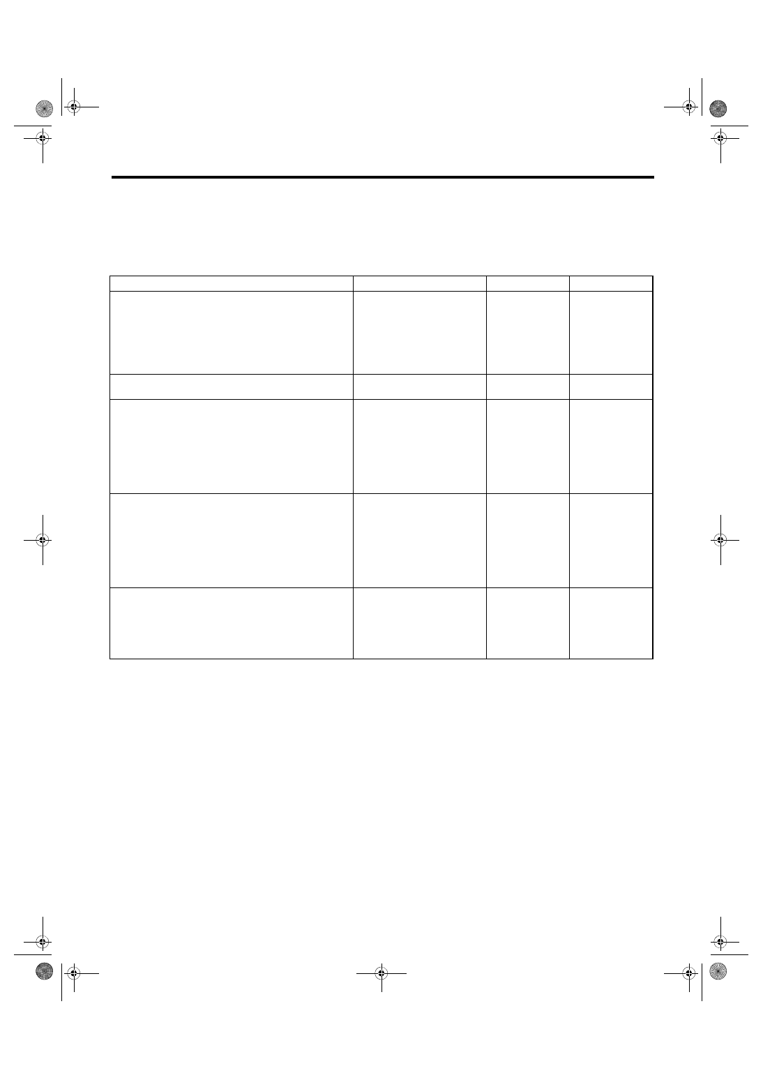
AJ:DTC C0057 ECM COMMUNICATION CIRCUIT
DTC DETECTING CONDITION:
No CAN signal from ECM.
TROUBLE SYMPTOM:
• ABS does not operate.
• VDC does not operate.
Step
Check
Yes
No
1
CHECK LAN SYSTEM.
Perform the diagnosis for LAN system. <Ref. to
LAN(diag)-2, Basic Diagnostic Procedure.>
Is there any fault in LAN sys-
tem?
2
CHECK POOR CONTACT OF CONNEC-
TORS.
Is there poor contact of ECM
connector?
Repair the connec-
tor.
3
CHECK ECM.
Refer to the basic diagnostic procedure of
ENGINE (DIAGNOSTICS).
Is ECM normal?
4
CHECK VDCCM&H/U.
1) Connect all connectors.
2) Clear the memory. <Ref. to VDC(diag)-27,
Clear Memory Mode.>
3) Perform the Inspection Mode. <Ref. to
VDC(diag)-26, Inspection Mode.>
4) Read the DTC.
Is the same DTC displayed?
5
CHECK OTHER DTC DETECTION.
Is any other DTC displayed?
It results from a
temporary noise
interference.
VDC(diag)-85
Diagnostic Procedure with Diagnostic Trouble Code (DTC)
VEHICLE DYNAMICS CONTROL (VDC) (DIAGNOSTICS)
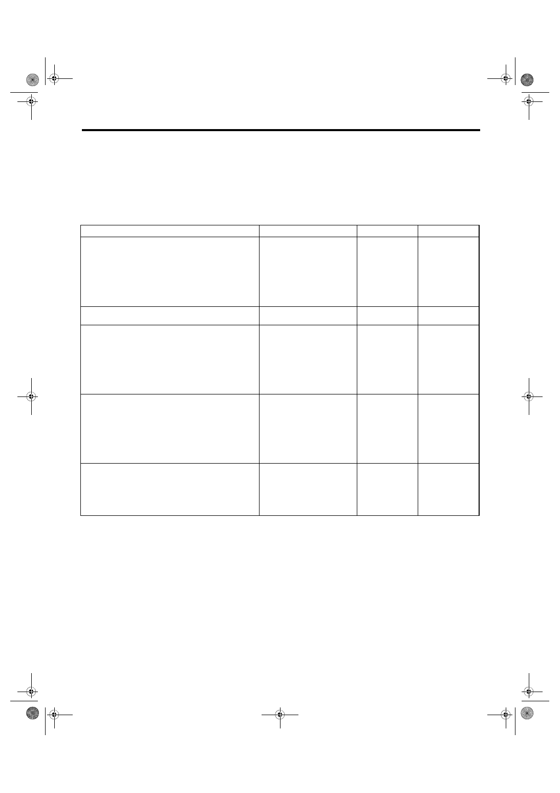
AK:DTC C0057 ECM CONTROL SYSTEM
DTC DETECTING CONDITION:
Cooperation control prohibition of ECM
TROUBLE SYMPTOM:
• ABS does not operate.
• VDC does not operate.
NOTE:
Warning lights go off if the cooperation control of ECM returns.
Step
Check
Yes
No
1
CHECK WARNING LIGHT.
Check whether the VDC warning light illumi-
nates after driving for 1 minute or more at a
speed of 10 km/h or more.
Does the VDC warning light illu-
minate?
VDC is normal.
Perform the Clear
Memory Mode.
NOTE:
DTC may be re-
corded if cranking
is performed dur-
ing driving.
2
CHECK POOR CONTACT OF CONNEC-
TORS.
Is there poor contact of ECM
connector?
Repair the connec-
tor.
3
CHECK ECM.
Refer to the basic diagnostic procedure of
ENGINE (DIAGNOSTICS).
Is ECM normal?
4
CHECK VDCCM&H/U.
1) Connect all connectors.
2) Perform the Clear Memory Mode. <Ref. to
VDC(diag)-27, Clear Memory Mode.>
3) Perform the Inspection Mode. <Ref. to
VDC(diag)-26, Inspection Mode.>
4) Read the DTC.
Is the same DTC displayed?
5
CHECK OTHER DTC DETECTION.
Is any other DTC displayed?
It results from a
temporary noise
interference.
VDC(diag)-86
Diagnostic Procedure with Diagnostic Trouble Code (DTC)
VEHICLE DYNAMICS CONTROL (VDC) (DIAGNOSTICS)
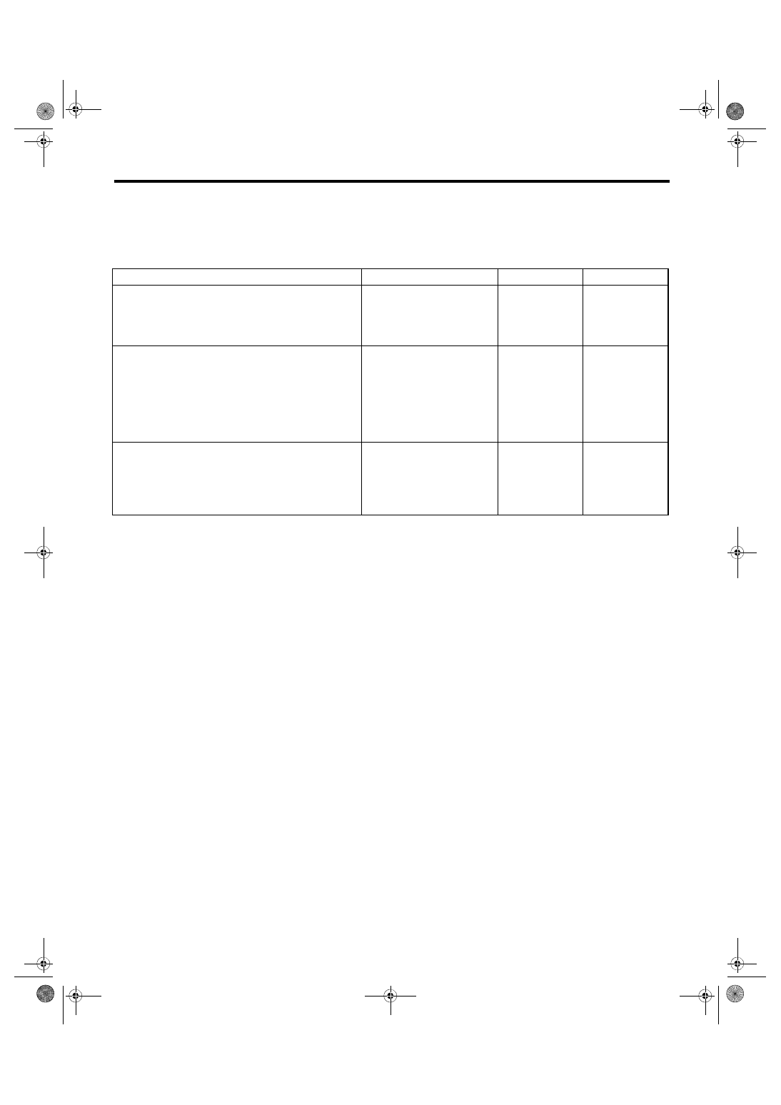
AL:DTC C0071 STEERING ANGLE SENSOR OFFSET IS TOO BIG
DTC DETECTING CONDITION:
Defective steering angle sensor
TROUBLE SYMPTOM:
VDC does not operate.
Step
Check
Yes
No
1
CHECK STEERING WHEEL.
1) Drive the vehicle on a flat road.
2) Park the vehicle straight.
3) Check the steering wheel for deviation from
center.
Is the deviation from the center
of steering wheel less than 5°?
Perform the cen-
tering adjustment
of steering wheel.
2
CHECK VDCCM&H/U.
1) Turn the ignition switch to OFF.
2) Connect all connectors.
3) Clear the memory. <Ref. to VDC(diag)-27,
Clear Memory Mode.>
4) Perform the Inspection Mode. <Ref. to
VDC(diag)-26, Inspection Mode.>
5) Read the DTC.
Is the same DTC displayed?
3
CHECK OTHER DTC DETECTION.
Is any other DTC displayed?
Temporary poor
contact occurs.
Нет комментариевНе стесняйтесь поделиться с нами вашим ценным мнением.
Текст