Subaru Impreza 3 / Impreza WRX / Impreza WRX STI. Service manual — part 793
WIRING SYSTEM
WI
Page
Basic Diagnostic Procedure . . . . . . . . . . . . . . . . . ...3
Working Precautions . . . . . . . . . . . . . . . . . . . . 14
Power Supply Circuit . . . . . . . . . . . . . . . . . . . . 15
Ground Circuit . . . . . . . . . . . . . . . . . . . . . . ..23
Engine Electrical System . . . . . . . . . . . . . . . . . . .32
Radiator Fan System . . . . . . . . . . . . . . . . . . . ...64
Charging System . . . . . . . . . . . . . . . . . . . . . ..65
Starter System . . . . . . . . . . . . . . . . . . . . . . .66
Vehicle Dynamics Control System . . . . . . . . . . . . . . ...67
Tire Pressure Monitoring System . . . . . . . . . . . . . . . .71
Driver’s Control Center Differential Control System . . . . . . . . .72
Air Conditioning System . . . . . . . . . . . . . . . . . . ...74
Airbag System . . . . . . . . . . . . . . . . . . . . . . ..82
Seat Belt Warning System . . . . . . . . . . . . . . . . . ...86
Occupant Detection System . . . . . . . . . . . . . . . . . .87
Seat Heater System . . . . . . . . . . . . . . . . . . . . .88
Headlight System . . . . . . . . . . . . . . . . . . . . . .90
Headlight Beam Leveler System . . . . . . . . . . . . . . . ..93
Front Fog Light System . . . . . . . . . . . . . . . . . . . 94
Back-up Light System . . . . . . . . . . . . . . . . . . . ..95
Stop Light System . . . . . . . . . . . . . . . . . . . . . 96
Clearance Light and Illumination Light System . . . . . . . . . . 98
Turn Signal Light and Hazard Light System . . . . . . . . . . ...103
Interior Light System . . . . . . . . . . . . . . . . . . . ..106
Front Wiper and Washer System . . . . . . . . . . . . . . ...109
Rear Wiper and Washer System . . . . . . . . . . . . . . . 110
Wiper Deicer System . . . . . . . . . . . . . . . . . . . .112
Audio System . . . . . . . . . . . . . . . . . . . . . . .113
Front Accessory Power Supply Socket System . . . . . . . . . .121
Rear Accessory Power Supply Socket System . . . . . . . . . ..122
Navigation System . . . . . . . . . . . . . . . . . . . . .123
Horn System . . . . . . . . . . . . . . . . . . . . . . ..129
Power Window System . . . . . . . . . . . . . . . . . . ..130
Remote Control Mirror System . . . . . . . . . . . . . . . ...134
Rear Defogger System . . . . . . . . . . . . . . . . . . ...135
Combination Meter System . . . . . . . . . . . . . . . . . 136
Speedometer System . . . . . . . . . . . . . . . . . . . .146
Clock System . . . . . . . . . . . . . . . . . . . . . . .147
Fuel Gauge System . . . . . . . . . . . . . . . . . . . ...148
Coolant Temperature System . . . . . . . . . . . . . . . . 149
Oil Pressure Warning Light System . . . . . . . . . . . . . ...150
Parking Brake / Brake Fluid Level Warning Light System . . . . . ..151
Rear Differential Oil Temperature Warning Light System . . . . . ..152
Sunroof Control System . . . . . . . . . . . . . . . . . . .153
Security System . . . . . . . . . . . . . . . . . . . . . .154
WI-2
WIRING SYSTEM
Immobilizer System . . . . . . . . . . . . . . . . . . . . 158
Keyless Entry System . . . . . . . . . . . . . . . . . . . 159
Cruise Control System . . . . . . . . . . . . . . . . . . ...163
CAN Communication System . . . . . . . . . . . . . . . . .171
Rearview Mirror System . . . . . . . . . . . . . . . . . . .173
Harness Components Location . . . . . . . . . . . . . . . ..174
Front Wiring Harness . . . . . . . . . . . . . . . . . . . .176
Bulkhead Wiring Harness (In Engine Compartment) . . . . . . . .178
Bulkhead Wiring Harness (In Compartment) . . . . . . . . . . .180
Engine Wiring Harness and Transmission Cord . . . . . . . . . 183
Instrument Panel Wiring Harness . . . . . . . . . . . . . . ..187
Rear Wiring Harness . . . . . . . . . . . . . . . . . . . ..189
Door Cord . . . . . . . . . . . . . . . . . . . . . . . ...192
Rear Wiring Harness and Trunk Lid Cord . . . . . . . . . . . ..194
Rear Wiring Harness and Rear Gate Cord . . . . . . . . . . . 196
WI-3
Basic Diagnostic Procedure
WIRING SYSTEM
1. Basic Diagnostic Procedure
A: BASIC PROCEDURES
1. GENERAL DESCRIPTION
The most important purpose of diagnostics is to
quickly determine which part is malfunctioning, to
save time and labor.
2. IDENTIFICATION OF TROUBLE SYMP-
TOM
Determine what the problem is based on the symp-
tom.
3. PROBABLE CAUSE OF TROUBLE
Look at the wiring diagram and check the system’s
circuit. Then check the switch, relay, fuse, ground,
etc.
4. LOCATION AND REPAIR OF TROUBLE
1) Using the diagnostics, narrow down the causes.
2) If necessary, use a voltmeter, ohmmeter, etc.
3) Before replacing certain component parts
(switch, relay, etc.), check the power supply,
ground, for open wiring harness, poor connectors,
etc. If no problem is encountered, check the com-
ponent parts.
5. SYSTEM OPERATION CHECK
After repairing, ensure that the system operates
properly.
B: BASIC INSPECTION
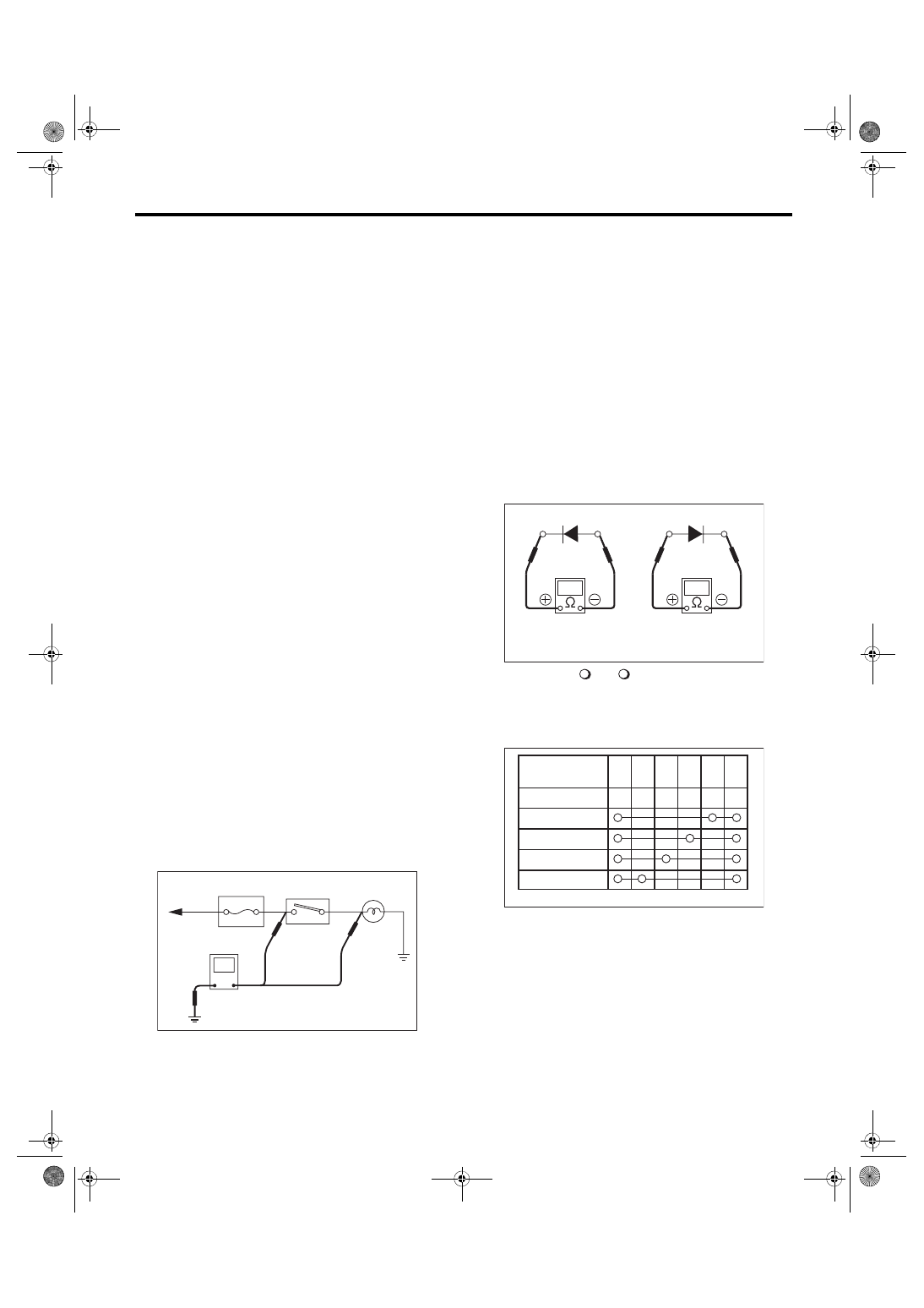
1. VOLTAGE MEASUREMENT
1) Using a voltmeter, connect the negative lead to a
good ground point or negative battery terminal and
the positive lead to the connector or component ter-
minal.
2) Contact the positive lead of the voltmeter on
connector (A). The voltmeter will indicate a voltage.
3) Touch connector (B) with the positive probe. The
voltmeter will indicate no voltage.
4) With the test set-up held as it is, turn the switch
to ON. The voltmeter will indicate a voltage and, at
the same time, the light will illuminate.
5) The circuit is in good order. If a problem such as
a light failing to illuminate occurs, use the proce-
dures outlined above to track down the malfunc-
tion.
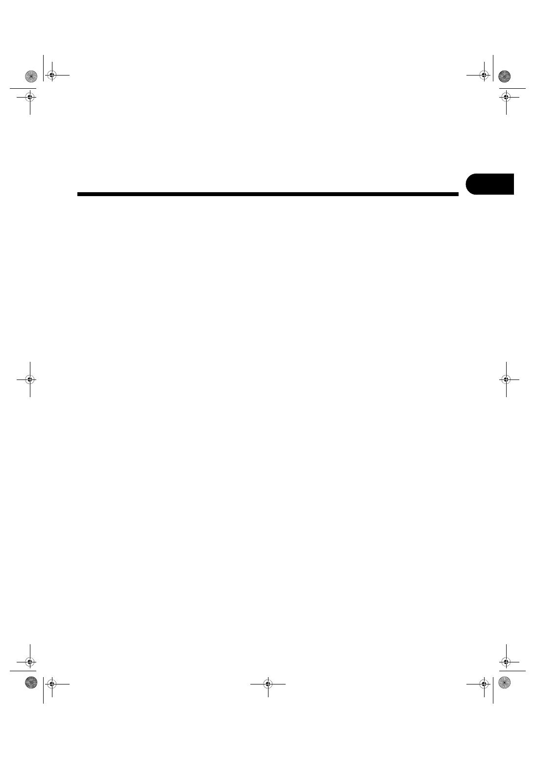
2. CIRCUIT CONTINUITY CHECKS
1) Disconnect the battery terminal or connector so
there is no voltage between the check points.
Contact the two leads of an ohmmeter to each of
the check points.
If the circuit has diodes, reverse the two leads and
check again.
2) Use an ohmmeter to check for diode continuity.
When contacting the negative lead to the diode
positive side and the positive lead to the negative
side, there should be continuity.
When contacting the two leads in reverse, there
should be no continuity.
3) The symbol “ — ” indicates that continuity
exists between two points or terminals. For exam-
ple, when a switch position is at “3”, continuity ex-
ists among terminals 1, 3 and 6, as shown in the
table below.
To power
Fuse
supply
Switch
Light
V
(A)
(B)
WI-02739
Continuity
No continuity
WI-02740
Terminal
Switch Position
OFF
1
2
3
4
1
2
3
4
5
6
WI-02741
WI-4
Basic Diagnostic Procedure
WIRING SYSTEM
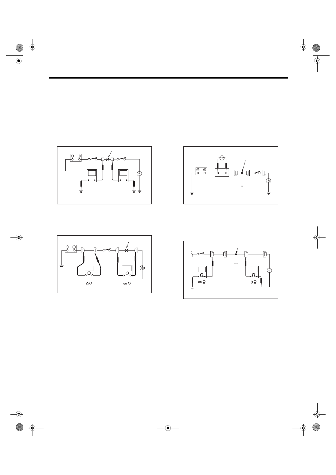
3. HOW TO DETERMINE AN OPEN CIR-
CUIT
1) WITH VOLTMETER:
An open circuit is determined by measuring the
voltage between respective connectors and ground
using a voltmeter, starting with the connector clos-
est to the power supply. The power supply must be
turned ON so that current flows in the circuit. If volt-
age is not present between a particular connector
and ground, the circuit between that connector and
the previous connector is open.
2) WITH OHMMETER:
Disconnect all connectors affected, and check con-
tinuity in the wiring between adjacent connectors.
When the ohmmeter indicates “infinite”, the wiring
is open.
4. HOW TO DETERMINE A SHORT CIR-
CUIT
1) WITH TEST LIGHT:
Connect a test light (rated at approx. 3 watts) in
place of the blown fuse and allow current to flow
through the circuit. Disconnect one connector at a
time from the circuit. Starting with the one located
farthest from the power supply. If the test light goes
out when a connector is disconnected, the wiring
between that connector and the next connector
(farther from the power supply) is shorted.
2) WITH OHMMETER:
Disconnect all affected connectors, and check con-
tinuity between each connector and ground. When
the ohmmeter indicates continuity between a par-
ticular connector and a ground, that connector is
shorted.
Open circuit or wiring
12V
V
V
0V
WI-02742
Open circuit
WI-09860
Shorted wiring
Test light
Fuse holder
WI-02744
Shorted connector
WI-02745
Нет комментариевНе стесняйтесь поделиться с нами вашим ценным мнением.
Текст