Subaru Impreza 3 / Impreza WRX / Impreza WRX STI. Service manual — part 410
5MT-61
Drive Pinion Shaft Assembly
MANUAL TRANSMISSION AND DIFFERENTIAL
NOTE:
If necessary, use a new gear and hub assembly as
a set, when replacing the gear or hub. Because
these must engage at the specified point, avoid dis-
assembly as much as possible. If it must be disas-
sembled, mark the engaging point on the spline
beforehand.
ST1 499757002
INSTALLER
ST2 899714110
REMOVER
D: ASSEMBLY
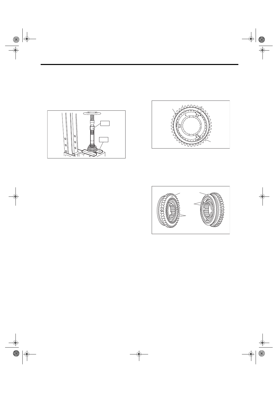
1) Install the sleeve and the gear and hub assem-
bly by matching the alignment marks.
NOTE:
• Make sure that there is no large clearance at
both sides of ball detent after assembly.
• Use the new gear & hub assembly, if replacing
the gear or hub.
MT-00251
ST1
ST2
(A) Ball detent
(B) 1st-2nd synchronizer hub
(C) Reverse driven gear
(D) There is no large clearance at this part.
(A) 1st gear side
(B) 2nd gear side
(C) Flush surface
(D) Stepped surface
MT-01639
(A)
(D)
(B)
(C)
MT-00252
( B )
( A )
( C )
( D )
5MT-62
Drive Pinion Shaft Assembly
MANUAL TRANSMISSION AND DIFFERENTIAL
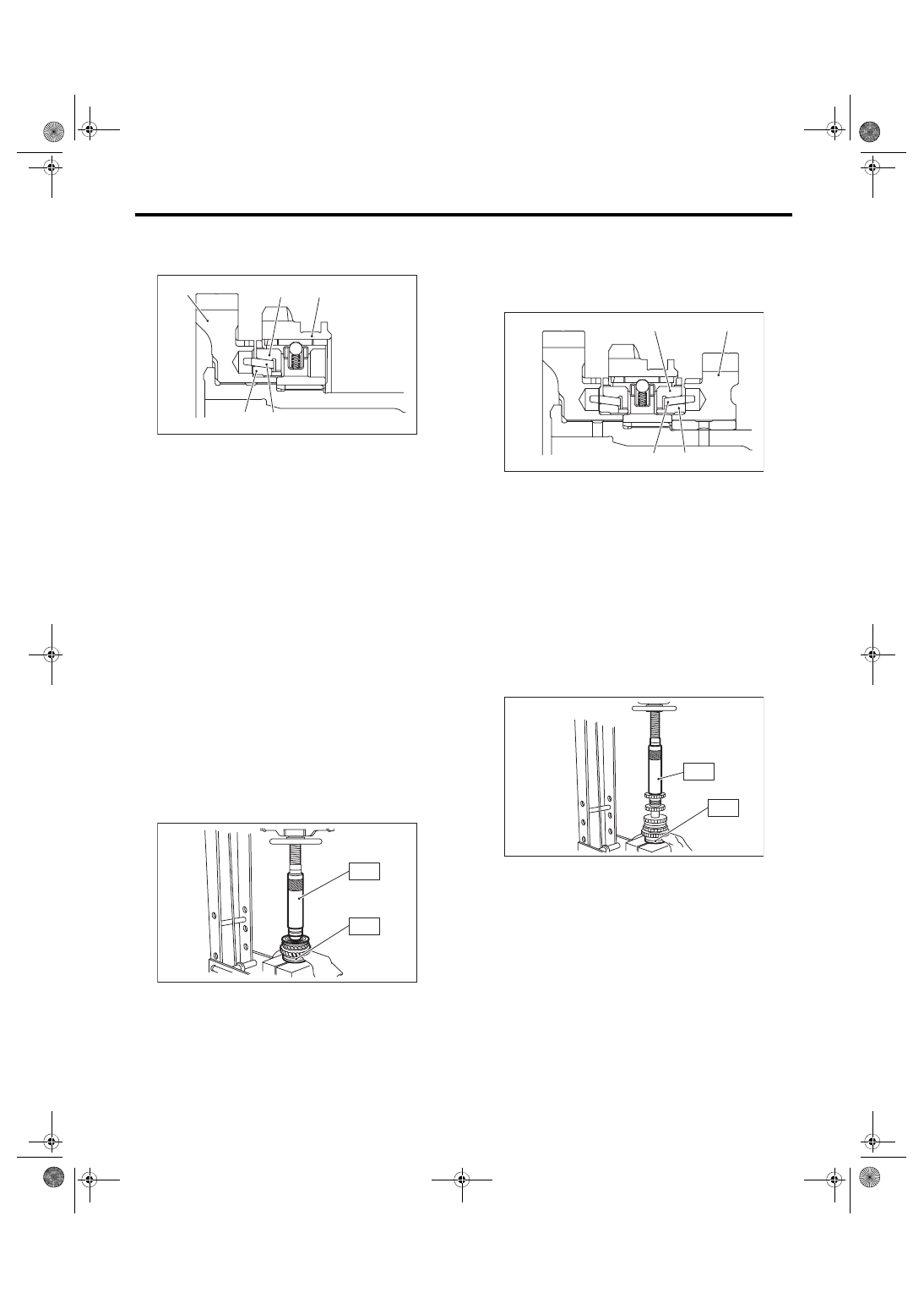
2) Install the 1st driven gear, inner baulk ring, syn-
chro cone, outer baulk ring, and gear & hub assem-
bly onto driven shaft.
NOTE:
• Take care to install the gear and hub assembly in
proper direction.
• Align the baulk ring and gear & hub assembly
with the key groove.
3) Install the 2nd driven gear bushing onto driven
shaft using ST1, ST2 and a press.
CAUTION:
Do not apply a load in excess of 10 kN (1 ton,
1.1 US ton, 1.0 Imp ton).
NOTE:
• Attach a cloth to the end of the driven shaft to
prevent damage.
• When press fitting, align the oil holes of the shaft
and bushing.
ST1 499277200
INSTALLER
ST2 499587000
INSTALLER
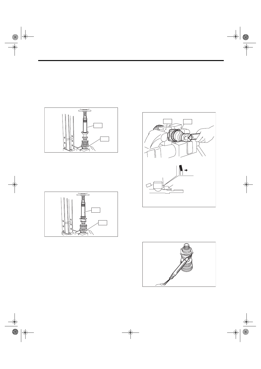
4) Install the 2nd driven gear, inner baulk ring, syn-
chro cone and outer baulk ring, and insert them
onto driven shaft.
NOTE:
Align the groove in baulk ring with the insert.
5) After installing key onto the driven shaft, install
the 3rd-4th driven gear using ST1, ST2 and a
press.
CAUTION:
Do not apply a load in excess of 10 kN (1 ton,
1.1 US ton, 1.0 Imp ton).
ST1 499277200
INSTALLER
ST2 499587000
INSTALLER
(A) 1st driven gear
(B) Synchro cone
(C) Inner baulk ring
(D) Outer baulk ring
(E) Gear & hub ASSY
MT-02398
(D)
(E)
(C)
(B)
(A)
MT-00253
ST1
ST2
(A) 2nd driven gear
(B) Synchro cone
(C) Inner baulk ring
(D) Outer baulk ring
(A)
(B)
(C)
(D)
MT-02396
MT-02403
ST1
ST2
5MT-63
Drive Pinion Shaft Assembly
MANUAL TRANSMISSION AND DIFFERENTIAL
6) Install a set of double taper roller bearings onto
the driven shaft using ST1, ST2 and a press.
CAUTION:
Do not apply a load in excess of 10 kN (1 ton,
1.1 US ton, 1.0 Imp ton).
NOTE:
Use a new double taper roller bearing.
ST1 499277200
INSTALLER
ST2 499587000
INSTALLER
7) Position the woodruff key in groove of the rear of
driven shaft. Install the 5th driven gear to the driven
shaft using ST1, ST2 and a press.
CAUTION:
Do not apply a load in excess of 10 kN (1 ton,
1.1 US ton, 1.0 Imp ton).
ST1 499277200
INSTALLER
ST2 499587000
INSTALLER
8) Install the lock washer. Tighten the lock nuts to
the specified torque using ST1 and ST2.
NOTE:
• Use new lock nuts and lock washers.
• Make sure the lock washer is installed in the
proper direction.
ST1 499987300
SOCKET WRENCH (50)
ST2 899884100
HOLDER
Tightening torque:
260 N·m (26.5 kgf-m, 191.8 ft-lb)
9) Using a spring scale, check that starting torque
of the double taper roller bearing is 0.1 to 1.5 N
(0.01 to 0.15 kgf, 0.02 to 0.34 lbf).
MT-02404
ST1
ST2
MT-02405
ST1
ST2
(A) Lock nut
(B) Lock washer
(C) Nut side
ST2
ST1
MT-02391
(A)
(B)
(C)
MT-00259
5MT-64
Drive Pinion Shaft Assembly
MANUAL TRANSMISSION AND DIFFERENTIAL
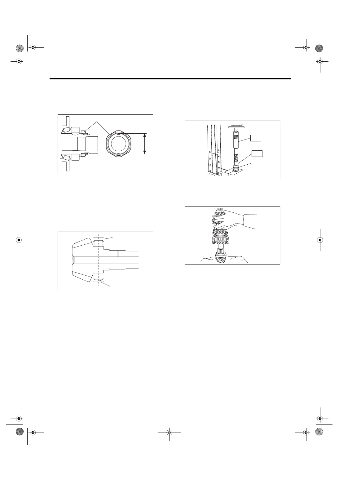
10) Crimp the lock nut at two locations so that the
dimension (B) becomes 41.1 mm (1.62 in) or less.
CAUTION:
When crimping the lock nut, be careful not to
crack it.
11) Install the roller bearing onto the drive pinion
shaft.
NOTE:
• Use a new roller bearing.
• When installing the roller bearing, direct the
knock pin hole of outer race toward rear.
12) Install the washer using ST1, ST2 and a press.
CAUTION:
Do not apply a load in excess of 10 kN (1 ton,
1.1 US ton, 1.0 Imp ton).
ST1 499277100
BUSHING 1-2 INSTALLER
ST2 499277200
INSTALLER
13) Install the thrust bearing and needle bearing.
Install the driven shaft assembly.
(A) Lock nut
(B) Outer dimension after crimping
(A) Roller bearing
(B) Knock pin hole
(B)
(A)
MT-02707
MT-00260
(A)
(B)
(A) Washer
MT-00261
(A)
ST1
ST2
MT-00262
Нет комментариевНе стесняйтесь поделиться с нами вашим ценным мнением.
Текст