Subaru Impreza 3 / Impreza WRX / Impreza WRX STI. Service manual — part 204
EN(H4DOTC)(diag)-40
Subaru Select Monitor
ENGINE (DIAGNOSTICS)
9. Subaru Select Monitor
A: OPERATION
1. HOW TO USE SUBARU SELECT MONI-
TOR
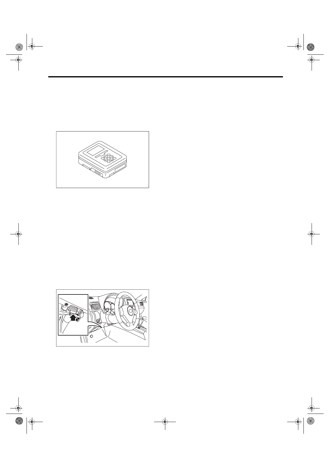
1) Prepare the Subaru Select Monitor kit. <Ref. to
EN(H4DOTC)(diag)-8, PREPARATION TOOL,
2) Prepare PC with Subaru Select Monitor in-
stalled.
3) Connect the USB cable to SDI (Subaru Diagno-
sis Interface) and USB port on the personal com-
puter (dedicated port for the Subaru Select
Monitor).
NOTE:
The dedicated port for the Subaru Select Monitor
means the USB port which was used to install the
Subaru Select Monitor.
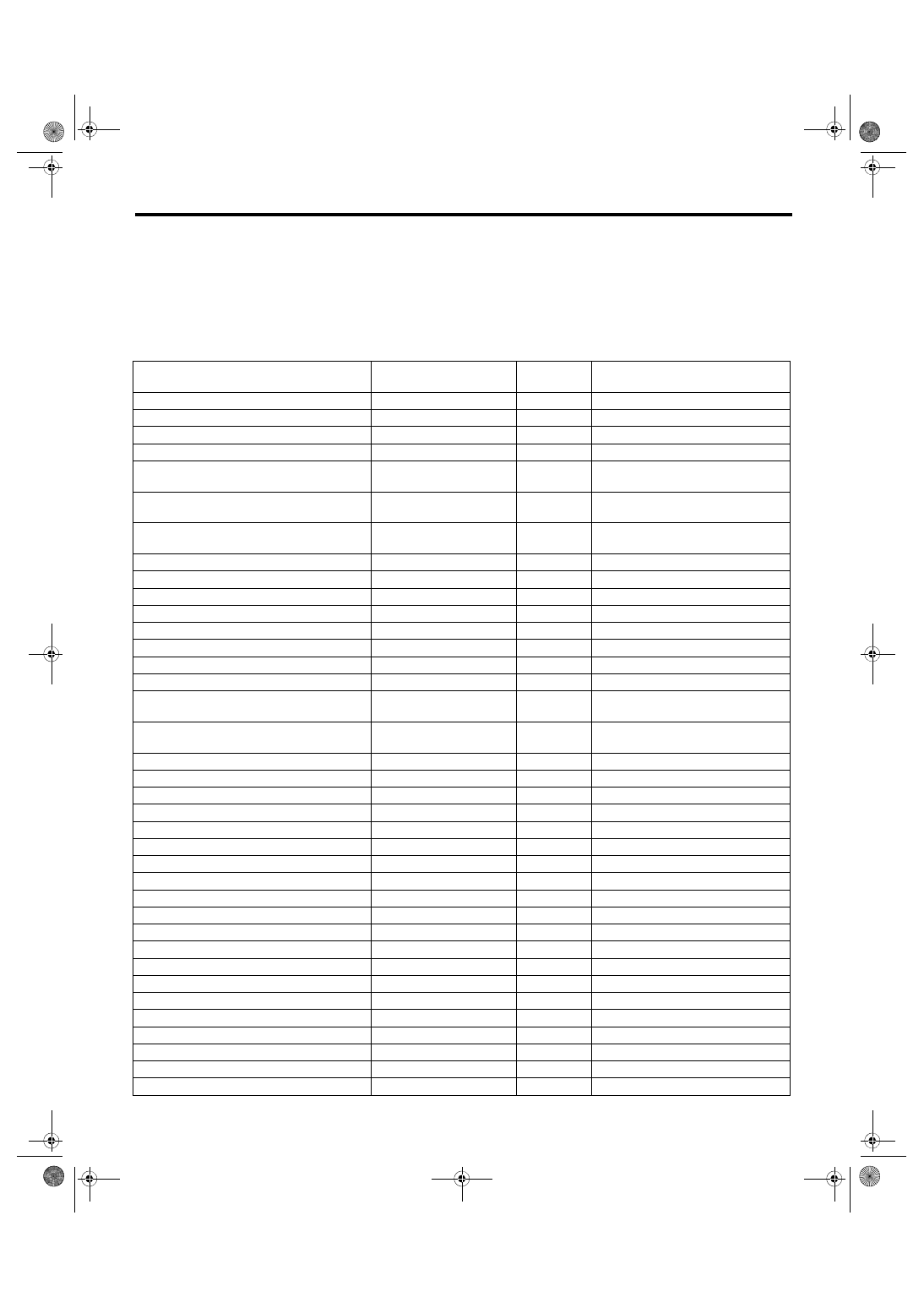
4) Connect the diagnosis cable to SDI.
5) Connect SDI to data link connector located in the
lower portion of the instrument panel (on the driv-
er’s side).
CAUTION:
Do not connect the scan tools except for Suba-
ru Select Monitor and general scan tool.
6) Start the PC.
7) Turn the ignition switch to ON (engine OFF) and
run the “PC application for Subaru Select Monitor”.
8) Call up DTC and data, then record them.
NOTE:
For detailed operation procedures, refer to “PC ap-
plication help for Subaru Select Monitor”.
EN-05692
EN-06148
EN(H4DOTC)(diag)-41
Subaru Select Monitor
ENGINE (DIAGNOSTICS)
2. READ CURRENT DATA FOR ENGINE (NORMAL MODE)
1) On «Main Menu» display, select {Each System Check}.
2) On «System Selection Menu» display, select {Engine Control System}.
3) Click the [OK] button after the information of engine type has been displayed.
4) On «Engine Diagnosis» display, select {Current Data Display & Save}.
5) On «Current Data Display & Save» display, select {Normal sampling}.
6) Using the scroll key, scroll the display screen up or down until the desired data is shown.
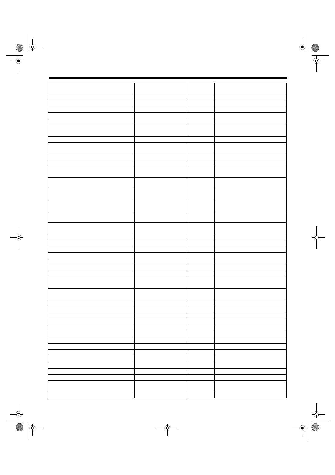
• A list of the support data is shown in the following table.
Contents
Display
Unit of mea-
sure
Note (at idling)
Engine load
Engine Load
%
21.0%
Engine coolant temperature signal
Coolant Temp.
°C or °F
80 — 100°C or 176 — 212°F
A/F correction #1
A/F Correction #1
%
–10 — +10%
A/F learning #1
A/F Learning #1
%
–15 — +15%
Intake manifold absolute pressure
Mani. Absolute Pressure
mmHg, kPa,
inHg or psig
220 — 275 mmHg, 29.5 — 37 kPa,
8.7 — 10 inHg or 4.2 — 5.3 psig
Engine speed signal
Engine Speed
rpm
630 — 770 rpm (Agree with the
tachometer indication)
Meter vehicle speed signal
Vehicle Speed
km/h or
MPH
0 km/h or 0 MPH (at parking)
Ignition timing signal
Ignition Timing
deg
10 — 15 deg
Intake air temperature signal
Intake Air Temp.
°C or °F
20 — 50°C or 68 — 122°F
Intake air amount
Mass Air Flow
g/s or lb/m
2.1 — 3.1 g/s or 0.35 — 0.40 lb/m
Throttle opening angle signal
Throttle Opening Angle
%
2.0 — 2.4%
Rear oxygen sensor voltage
Rear O2 Sensor
V
0 — 1.0 V
Battery voltage
Battery Voltage
V
12 — 15 V
Mass air flow voltage
Air Flow Sensor Voltage
V
1.0 — 1.7 V
Injection 1 pulse width
Fuel Injection #1 Pulse
ms
1.2 — 2.2 ms
Atmospheric pressure
Atmospheric pressure
mmHg, kPa,
inHg or psig
—
Intake manifold relative pressure
Mani. Relative Pressure
mmHg, kPa,
inHg or psig
Air intake absolute pressure — Atmo-
spheric pressure
Learned value of ignition timing
Learned Ignition Timing
deg
0 deg
Acceleration opening angle signal
Accel opening angle
%
0.0%
Boost control solenoid valve duty ratio
Primary Control
%
0.0%
Purge control solenoid duty ratio
CPC Valve Duty Ratio
%
0 — 25%
Tumble generator valve RH opening signal
TGV Position Sensor R
V
0.81 V
Tumble generator valve LH opening signal
TGV Position Sensor L
V
0.81 V
Fuel pump duty ratio
Fuel Pump Duty
%
30 — 40%
AVCS advance angle amount RH
VVT Adv. Ang. Amount R
deg
±5 deg
AVCS advance angle amount LH
VVT Adv. Ang. Amount L
deg
±5 deg
Oil flow control solenoid valve duty ratio RH
OCV Duty R
%
0 — 20%
Oil flow control solenoid valve duty ratio LH
OCV Duty L
%
0 — 20%
Oil flow control solenoid valve current RH
OCV Current R
mA
40 — 100 mA
Oil flow control solenoid valve current LH
OCV Current L
mA
40 — 100 mA
A/F sensor current value 1
A/F Sensor #1 Current
mA
–20 — 20 mA
A/F sensor resistance value 1
A/F Sensor #1 Resistance
Ω
27 — 35 Ω
A/F sensor output lambda 1
A/F Sensor #1
—
1.0
A/F correction #3
A/F Correction #3
%
0.00%
A/F learning #3
A/F Learning #3
%
0.00%
SI drive mode (model with SI-DRIVE)
SI Drive Mode
—
I, S or S#
Throttle motor duty
Throttle Motor Duty
%
–5%
EN(H4DOTC)(diag)-42
Subaru Select Monitor
ENGINE (DIAGNOSTICS)
Throttle motor voltage
Throttle Motor Voltage
V
12 — 15 V
Sub throttle sensor voltage
Sub-Throttle Sensor
V
1.5 V
Main throttle sensor voltage
Main-Throttle Sensor
V
0.6 V
Sub accelerator sensor voltage
Sub-Accelerator Sensor
V
1.1 V
Main acceleration sensor voltage
Main-Accelerator Sensor
V
1.0 V
Secondary air supply piping pressure signal
Sec. Air Piping Pressure
mmHg, kPa,
inHg or psig
765 mmHg, 102 kPa, 30.1 inHg or
14.8 psig
Secondary airflow signal
Sec. Air Flow
g/s or lb/m
0.00 g/s or 0.00 lb/m
Memory vehicle speed
Memorized Cruise Speed
km/h or
MPH
—
Fuel level sensor resistance
Fuel level resistance
Ω
4 — 96 Ω
Odometer
Odometer
km
—
Exhaust AVCS retard angle amount RH
(model with SI-DRIVE)
Exh. VVT Retard Ang. R
deg
±5 deg
Exhaust AVCS retard angle amount LH
(model with SI-DRIVE)
Exh. VVT Retard Ang. L
deg
±5 deg
Exhaust oil flow control solenoid valve duty
ratio RH (model with SI-DRIVE)
Exh. OCV Duty R
%
0 — 20%
Exhaust oil flow control solenoid valve duty
ratio LH (model with SI-DRIVE)
Exh. OCV Duty L
%
0 — 20%
Exhaust oil flow control solenoid valve cur-
rent value RH (model with SI-DRIVE)
Exh. OCV Current R
mA
40 — 100 mA
Exhaust oil flow control solenoid valve cur-
rent value LH (model with SI-DRIVE)
Exh. OCV Current L
mA
40 — 100 mA
#1 cylinder roughness monitor
Roughness Monitor #1
—
0
#2 cylinder roughness monitor
Roughness Monitor #2
—
0
#3 cylinder roughness monitor
Roughness Monitor #3
—
0
#4 cylinder roughness monitor
Roughness Monitor #4
—
0
Knock sensor correction
Knocking Correction
deg
0.0 deg
AT/MT identification terminal
AT Vehicle ID Signal
—
OFF
D-check require Flag
D-check Require Flag
—
OFF
Delivery (test) mode terminal
Delivery Mode Connector
(Test Mode Connector)
—
OFF
Neutral position switch signal
Neutral Position Switch
Signal
—
Neutral
Soft idle switch signal
Idle Switch Signal
—
Idle
Ignition switch signal
Ignition Switch
—
ON
Power steering switch signal
P/S Switch
—
OFF (when OFF)
Air conditioning switch signal
A/C Switch
—
OFF (when OFF)
Starter switch signal
Starter Switch
—
OFF
Rear oxygen monitor
Rear O2 Rich Signal
—
ON/OFF
Knocking signal
Knocking Signal
—
No Support
Crankshaft position sensor signal
Crankshaft Position Sig.
—
Support
Camshaft position sensor signal
Camshaft Position Sig.
—
Support
Rear defogger switch signal
Rear Defogger SW
—
OFF (when OFF)
Blower fan switch signal
Blower Fan SW
—
OFF (when OFF)
Light switch signal
Light Switch
—
OFF (when OFF)
Air conditioner middle pressure switch signal
A/C Mid Pressure Switch
—
OFF (when OFF)
Air conditioner compressor relay output sig-
nal
A/C Compressor Signal
—
OFF (when OFF)
Radiator fan relay 1 signal
Radiator Fan Relay #1
—
OFF (when OFF)
Contents
Display
Unit of mea-
sure
Note (at idling)
EN(H4DOTC)(diag)-43
Subaru Select Monitor
ENGINE (DIAGNOSTICS)
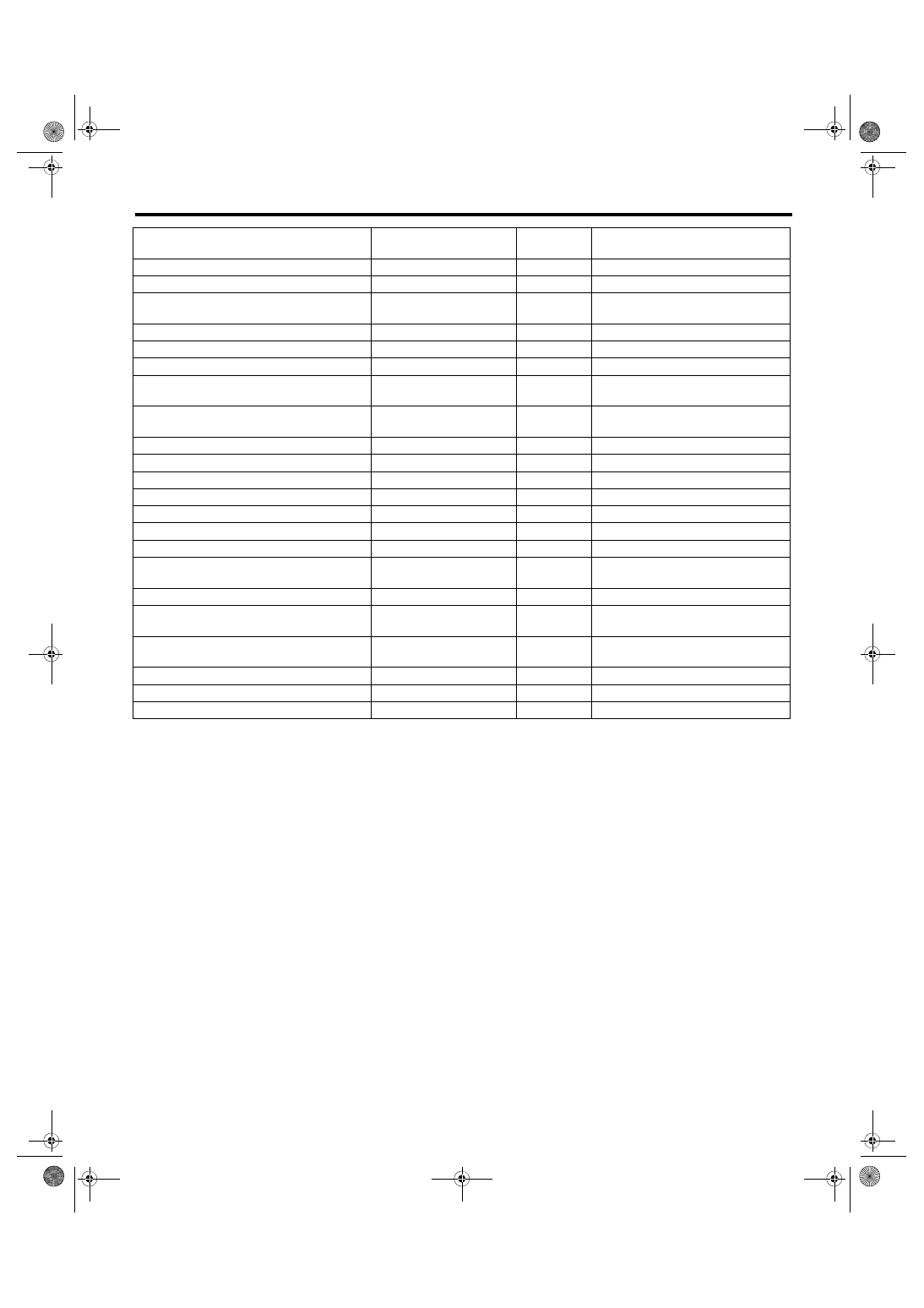
NOTE:
• For detailed operation procedures, refer to “PC application help for Subaru Select Monitor”.
• *: For models without cruise control, the brake switch signal does not change.
Radiator fan relay 2 signal
Radiator Fan Relay #2
—
OFF (when OFF)
PCV hose assembly diagnosis signal
Blow-by leak Connector
—
ON
Pressure control solenoid valve assembly
signal
PCV Solenoid Valve
—
OFF (when OFF)
Tumble generator valve output signal
TGV Output
—
No Support
Tumble generator valve driving signal
TGV Drive
—
Close
Purge control solenoid valve 2 signal
CPC Solenoid 2
—
OFF (when OFF)
Vehicle dynamics control (VDC) torque down
prohibition output
Ban of Torque Down
—
OK
Vehicle dynamics control (VDC) torque down
demand
Request Torque Down
VDC
—
No Support
ETC motor relay signal
ETC Motor Relay
—
ON
Clutch switch signal
Clutch Switch
—
OFF (when OFF)
Stop light switch signal
Stop Light SW
—
OFF (when OFF)
SET/COAST switch signal
SET/COAST SW
—
OFF (when OFF)
RES/ACC switch signal
RESUME/ACCEL SW
—
OFF (when OFF)
Brake switch signal*
Brake Switch Signal
—
OFF (when OFF)
Main switch signal
Main Switch Signal
—
OFF (when OFF)
Secondary air combination valve relay 2 sig-
nal
Sec. Air Combi V Relay 2
—
OFF (when OFF)
Secondary air pump relay signal
Sec. Air Pump Relay
—
OFF (when OFF)
Secondary air combination valve relay 1 sig-
nal
Sec. Air Combi V Relay 1
—
OFF (when OFF)
Cruise control cancel switch signal
Cruise Control Cancel
Switch Signal
—
OFF (when OFF)
Malfunction indicator light signal
MIL On Flag
—
OFF (when unlit)
ELCM switching valve drive signal
ELCM switching valve
—
Open
ELCM vacuum pump drive signal
ELCM pump
—
OFF
Contents
Display
Unit of mea-
sure
Note (at idling)
Нет комментариевНе стесняйтесь поделиться с нами вашим ценным мнением.
Текст