Subaru Impreza 3 / Impreza WRX / Impreza WRX STI. Service manual — part 431
6MT-61
Transmission Case
MANUAL TRANSMISSION AND DIFFERENTIAL
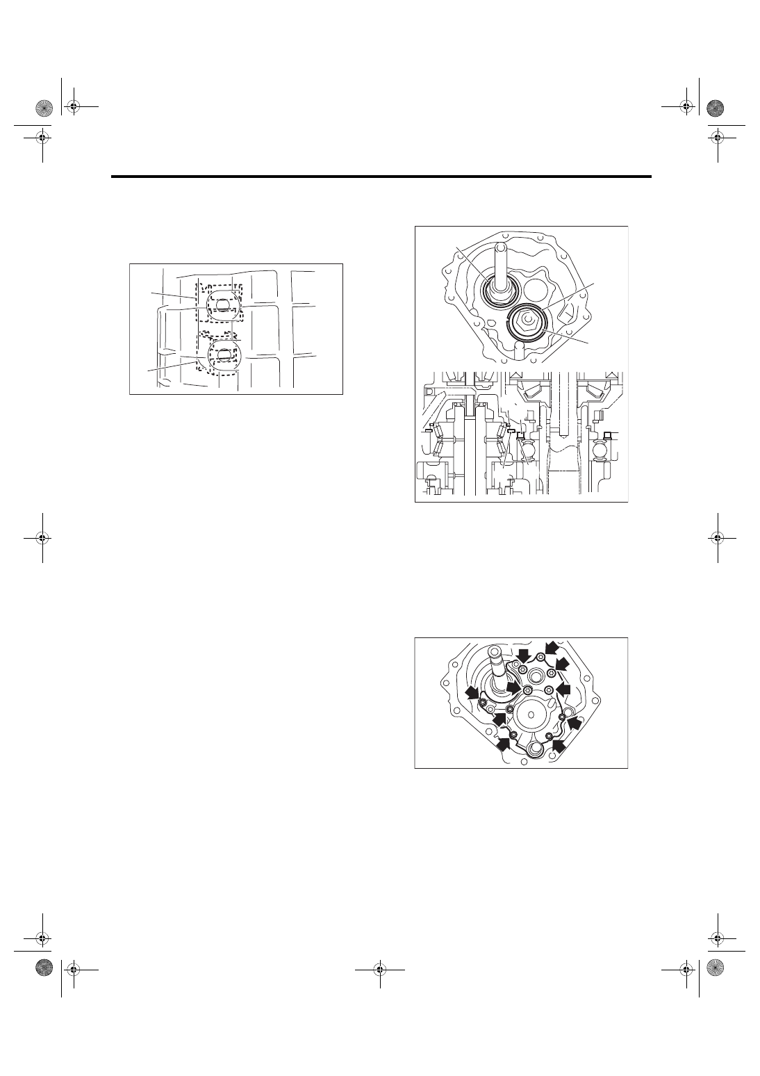
4) By inspecting from the pilot bolt attachment hole,
check that the interlock block and the reverse inter-
lock block are aligned to the neutral position. If not
aligned, remove the transmission case, and shift
the shifter fork and interlock block to the neutral po-
sition.
5) Use a new gasket to temporarily attach the pilot
bolt.
6) Affix the transmission case with the bolts and
nuts.
Tightening torque:
50 N·m (5.1 kgf-m, 36.9 ft-lb)
7) Tighten the pilot bolt.
Tightening torque:
34 N·m (3.5 kgf-m, 25.1 ft-lb)
8) Tighten the holder reverse bolt.
Tightening torque:
25 N·m (2.5 kgf-m, 18.4 ft-lb)
9) Install the snap ring and washer for the main
shaft assembly, and washer and collar for the driv-
en gear assembly.
10) Install the transfer bearing holder.
Tightening torque:
25 N·m (2.5 kgf-m, 18.4 ft-lb)
ST 18663AA000 SOCKET
11) When replacing the transfer bearing holder, se-
lect the appropriate transfer driven gear and adjust-
ing washer, and install to the extension case. <Ref.
to 6MT-45, ADJUSTMENT, Extension Case.>
(A) Interlock block
(B) Reverse interlock block
MT-00533
(A)
(B)
(A) Washer
(B) Snap ring
(C) Collar
(D) Washer
(C)
(B)
(A)
(C)
(B)
(D)
(A)
MT-01621
MT-01619
6MT-62
Transmission Case
MANUAL TRANSMISSION AND DIFFERENTIAL
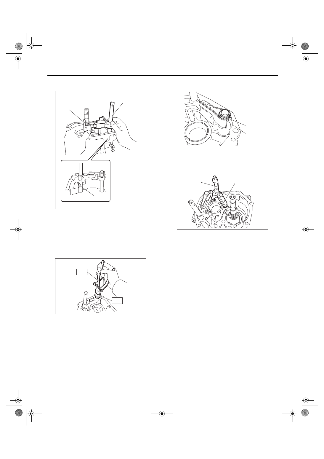
12) Install the selector arm No. 2, shifter arm, se-
lector plunger and spring.
13) Install a new straight pin.
14) Using the ST, install the neutral set spring.
ST1 18756AA000
CLAW
ST2 399893600
PLIER
15) Install the snap ring and flat washer to the se-
lector arm area.
16) Install the oil guides G and H.
17) Install the center differential. <Ref. to 6MT-57,
INSTALLATION, Center Differential.>
18) Install the transfer driven gear. <Ref. to 6MT-
55, INSTALLATION, Transfer Driven Gear.>
19) Install the extension case. <Ref. to 6MT-43, IN-
20) Install the neutral position switch, back-up light
switch and harness. <Ref. to 6MT-41, INSTALLA-
TION, Neutral Position Switch.> <Ref. to 6MT-39,
INSTALLATION, Back-up Light Switch.>
21) Install the manual transmission assembly to the
vehicle. <Ref. to 6MT-33, INSTALLATION, Manual
(A) Selector arm No. 2
(B) Shifter arm
(C) Selector plunger
MT-02713
(B)
(A)
(C)
MT-01092
ST2
ST1
(A) Snap ring
(B) Flat washer
(A) Oil guide G
(B) Oil guide H
MT-01616
(B)
(A)
MT-01728
(A)
(B)
6MT-63
Transmission Case
MANUAL TRANSMISSION AND DIFFERENTIAL
C: DISASSEMBLY
1) Remove the transmission harness from the
transmission case.
NOTE:
Remove the connector by disengaging the connec-
tor claw from the inside of the transmission.
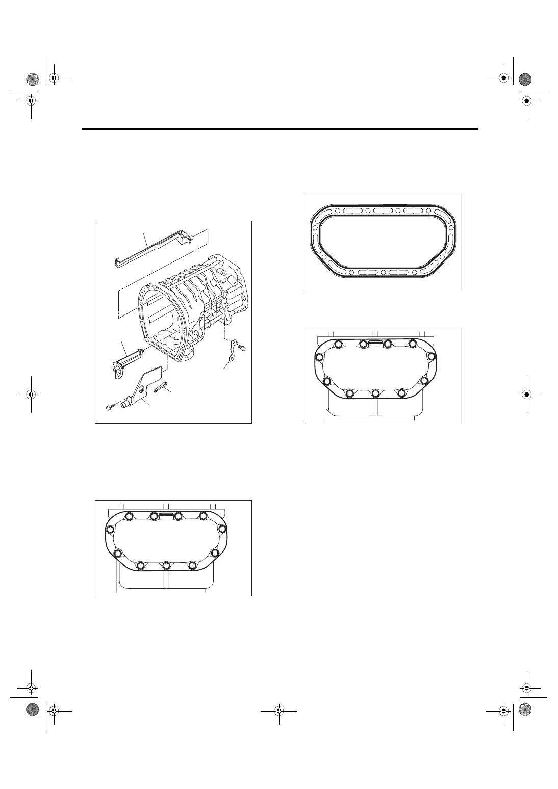
2) Remove the oil guides C, D, E, F and harness
bracket.
3) Remove the oil pan.
4) Remove any remaining liquid gasket from the
transmission case and oil pan.
D: ASSEMBLY
1) Apply liquid gasket to the oil pan.
Liquid gasket:
THREE BOND 1215 (Part No. 004403007) or
equivalent
2) Install the oil pan.
Tightening torque:
6.4 N·m (0.7 kgf-m, 4.7 ft-lb)
(A) Oil guide C
(B) Oil guide D
(C) Oil guide E
(D) Oil guide F
(E) Harness bracket
(A)
(B)
(C)
(D)
MT-01712
(E)
MT-01831
MT-00541
MT-01831
6MT-64
Transmission Case
MANUAL TRANSMISSION AND DIFFERENTIAL
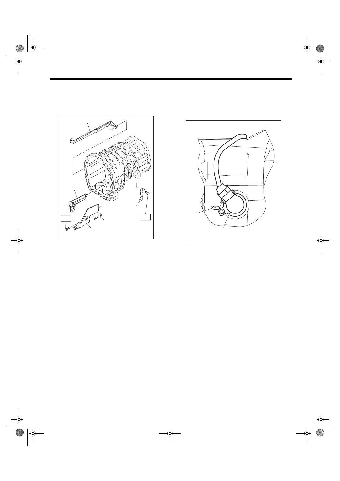
3) Install the oil guides C, D, E, F and harness
bracket.
Tightening torque:
T1: 16 N·m (1.6 kgf-m, 11.8 ft-lb)
T2: 18 N·m (1.8 kgf-m, 13.3 ft-lb)
4) Attach the transmission harness to the transmis-
sion.
NOTE:
Install the transmission harness connector by align-
ing the protrusions of the transmission and trans-
mission harness connector.
E: INSPECTION
1) If the sludge is accumulated in the oil pan, use a
waste cloth to wipe it off completely.
2) Check that there is no damage on any parts. Re-
place damaged parts with new parts.
(A) Oil guide C
(B) Oil guide D
(C) Oil guide E
(D) Oil guide F
(E) Harness bracket
(A)
(B)
(C)
(D)
MT-01713
(E)
T1
T2
(A) Protrusion
(B) Transmission harness connectors
MT-01777
(B)
(A)
Нет комментариевНе стесняйтесь поделиться с нами вашим ценным мнением.
Текст