Subaru Impreza 3 / Impreza WRX / Impreza WRX STI. Service manual — part 691
COM-3
Horn System
COMMUNICATION SYSTEM
2. Horn System
A: WIRING DIAGRAM
Refer to “Horn System” in the wiring diagram. <Ref. to WI-129, WIRING DIAGRAM, Horn System.>
B: INSPECTION
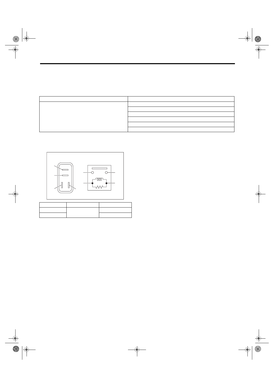
1. HORN RELAY
1) Connect terminal No. 4 to the battery positive terminal and the terminal No. 3 to the battery negative ter-
minal, and check the resistance value between the horn relay terminals.
2) Replace the horn relay if the inspection result is not within the standard value.
C: NOTE
For procedure of each component in the horn system, refer to the respective section.
• Horn assembly: <Ref. to COM-4, Horn.>
• Horn switch: <Ref. to COM-5, Horn Switch.>
Symptoms
Inspection steps
Horn does not sound
1. Check the fuse.
2. Check the horn relay.
3. Check the role connector.
4. Check the horn switch.
5. Check the horn assembly.
6. Check the harness.
Continuity
Terminal No.
Standard value
Yes
1 and 2
Less than 1 Ω
None
1 MΩ or more
COM00001
(1)
(2)
(1)
(4)
(2)
(3)
(3)
(4)
COM-4
Horn
COMMUNICATION SYSTEM
3. Horn
A: REMOVAL
1) Disconnect the ground cable from battery.
2) Remove the front bumper face. <Ref. to EI-31,
FRONT BUMPER FACE, REMOVAL, Front
3) Disconnect the harness connector.
4) Remove the horn bracket mounting bolt, and re-
move the horn assembly.
B: INSTALLATION
1) Install each part in the reverse order of removal.
Tightening torque:
Lo side: 18 N·m (1.84 kgf-m, 13.3 ft-lb)
Hi side: 13 N·m (1.33 kgf-m, 9.6 ft-lb)
2) Adjust the fog light beam. (Model with fog light)
<Ref. to LI-21, FOG LIGHT AIMING, ADJUST-
MENT, Front Fog Light Assembly.>
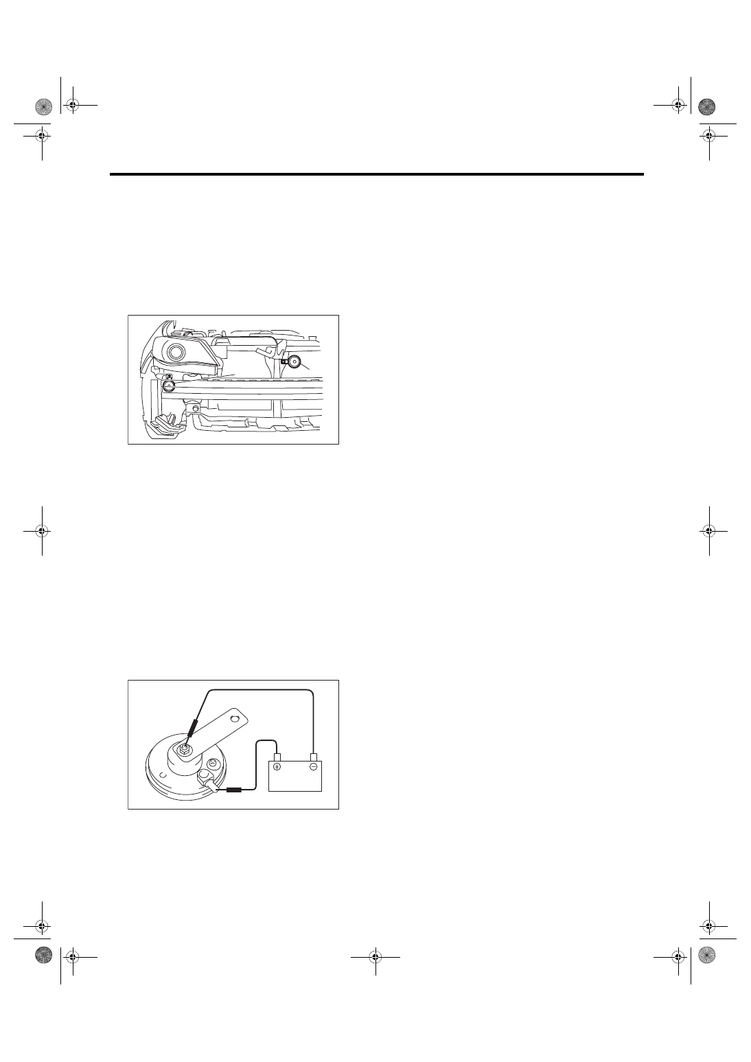
C: INSPECTION
1) Remove the horn. <Ref. to COM-4, REMOVAL,
2) Check the horn sounds when applying the bat-
tery voltage to the horn assembly.
3) If it does not operate normally, replace the horn
assembly.
(1) Lo side horn
(2) Hi side horn
COM00057
(1)
(2)
COM00003
COM-5
Horn Switch
COMMUNICATION SYSTEM
4. Horn Switch
A: REMOVAL
CAUTION:
Before handling the airbag module, refer to
“CAUTION” of “General Description” in “AIR-
BAG SYSTEM”. <Ref. to AB-5, CAUTION, Gen-
eral Description.>
NOTE:
Horn switch is a unit with the driver’s airbag mod-
ule.
1) Disconnect the ground cable from battery and
wait for at least 60 seconds before starting work.
2) Remove the driver’s airbag module. <Ref. to AB-
15, REMOVAL, Driver’s Airbag Module.>
B: INSTALLATION
CAUTION:
• Before handling the airbag module, refer to
“CAUTION” of “General Description” in “AIR-
BAG SYSTEM”. <Ref. to AB-5, CAUTION, Gen-
• Do not allow harness and connectors to in-
terfere or get tangled up with other parts.
1) Install the driver’s airbag module. <Ref. to AB-
15, INSTALLATION, Driver’s Airbag Module.>
2) Install each part in the reverse order of removal.
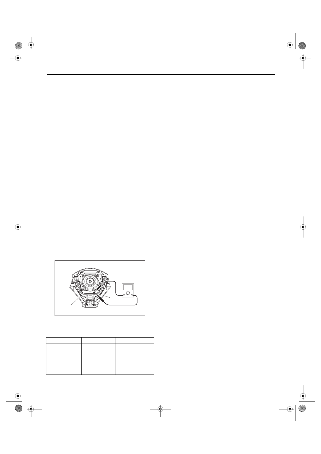
C: INSPECTION
1) Remove the horn switch. <Ref. to COM-5, RE-
2) Check the resistance between horn switch termi-
nal and airbag module bracket.
3) Replace the driver’s airbag module if the inspec-
tion result is not within the standard value.
(1) Horn switch terminal
(2) Airbag module bracket
Switch position
Terminal No.
Standard value
The airbag mod-
ule bracket being
pushed
Horn switch ter-
minal and airbag
module bracket
Less than 1 Ω
The airbag mod-
ule bracket being
separated
1 MΩ or more
COM00055
(2)
(1)
COM-6
Horn Switch
COMMUNICATION SYSTEM
Нет комментариевНе стесняйтесь поделиться с нами вашим ценным мнением.
Текст