Subaru Impreza 3 / Impreza WRX / Impreza WRX STI. Service manual — part 73
ME(STI)-54
Timing Belt
MECHANICAL
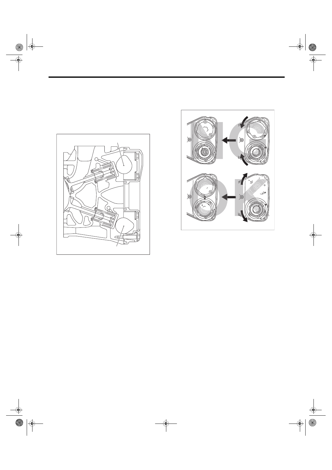
7) Make sure that the cam and crank sprockets are
positioned properly.
CAUTION:
• Intake and exhaust camshafts for this DOHC
engine can be independently rotated with the
timing belts removed. As can be seen from the
figure, if the intake and exhaust valves are lifted
simultaneously, heads will interfere with each
other, resulting in bent valves.
• When the timing belts are not installed, four
camshafts are held at the “zero-lift” position,
where all cams on camshafts are not pushing
down on the intake and exhaust valves. (Under
this condition, all valves remain unlifted.)
• When the camshafts are rotated to install the
timing belts, #2 intake and #4 exhaust cam of
camshaft LH are held, pushing their corre-
sponding valves down. (Under this condition,
these valves are held lifted.) Camshaft RH are
held so that their cams do not push the valves
down.
• Camshafts LH must be rotated from the zero-
lift position to the position where the timing belt
is to be installed with the smallest possible an-
gle, in order to prevent mutual interference of
intake and exhaust valve heads.
• Do not allow the camshafts to rotate in the di-
rection shown in the upper figure. Doing this
may cause both the intake and exhaust valves
to lift simultaneously, resulting in mutual inter-
ference of valve heads.
(A) Intake camshaft
(B) Exhaust camshaft
ME-04111
(A)
(B)
(A) Direction of rotation
(B) Timing belt installation position
(A)
(A)
(A)
(A)
(B)
(B)
ME-04717
ME(STI)-55
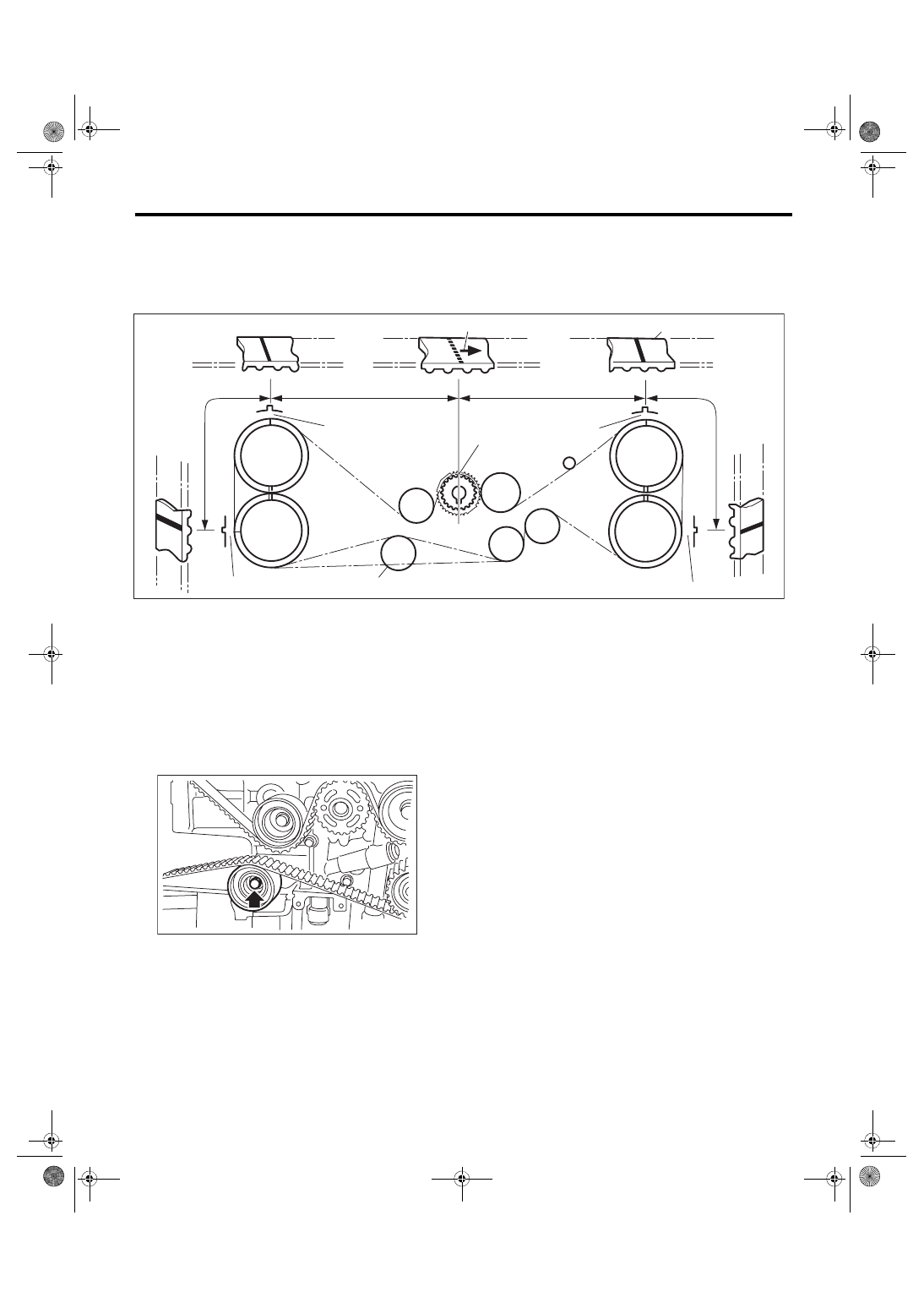
Timing Belt
MECHANICAL
8) Align the alignment mark on the timing belt with marks on the sprockets in the alphabetical order shown
in the figure. While aligning marks, position the timing belt properly, and install the timing belt.
CAUTION:
• If the timing belt slips by 1 or more teeth, the valve and piston may hit each other.
• Make sure that the direction of belt rotation is correct.
9) Install the belt idlers.
Tightening torque:
39 N·m (4.0 kgf-m, 28.8 ft-lb)
NOTE:
Make sure that the marks on the timing belt and
sprockets are aligned.
(1)
Arrow mark
(4)
54.5 teeth
(6)
28 teeth
(2)
Timing belt
(5)
51 teeth
(7)
Install it in the end
(3)
28 teeth
ME-04718
(1)
(2)
(5)
(6)
(4)
(D)
(A)
(C)
(B)
(E)
(3)
RH-IN
RH-EX
LH-EX
LH-IN
(7)
ME-04982
ME(STI)-56
Timing Belt
MECHANICAL
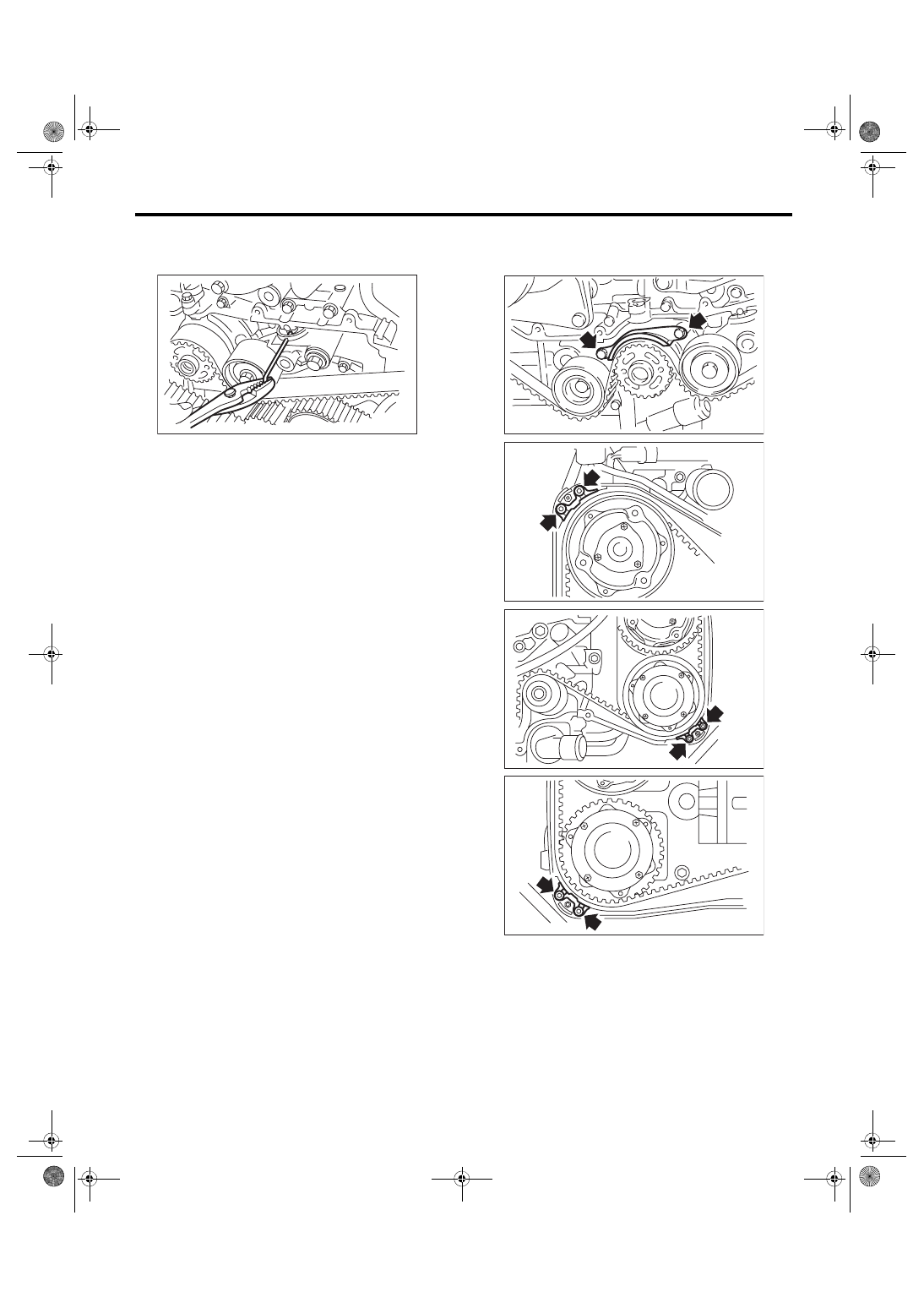
10) After ensuring that the marks on the timing belt
and sprockets are aligned, remove the stopper pin
from tensioner adjuster.
11) Install the timing belt guide.
(1) Temporarily tighten the bolts mounting the
timing belt guide.
NOTE:
• Before installing the timing belt guide, clean the
timing belt guide mounting bolt holes of the timing
belt cover No. 2.
• Apply liquid gasket to the thread of the timing belt
guide mounting bolt on the cam sprocket section.
(when reusing bolts)
Liquid gasket:
THREE BOND 1324 (Part No. 004403042) or
equivalent
ME-00245
ME-00230
ME-03124
ME-03125
ME-03126
ME(STI)-57
Timing Belt
MECHANICAL
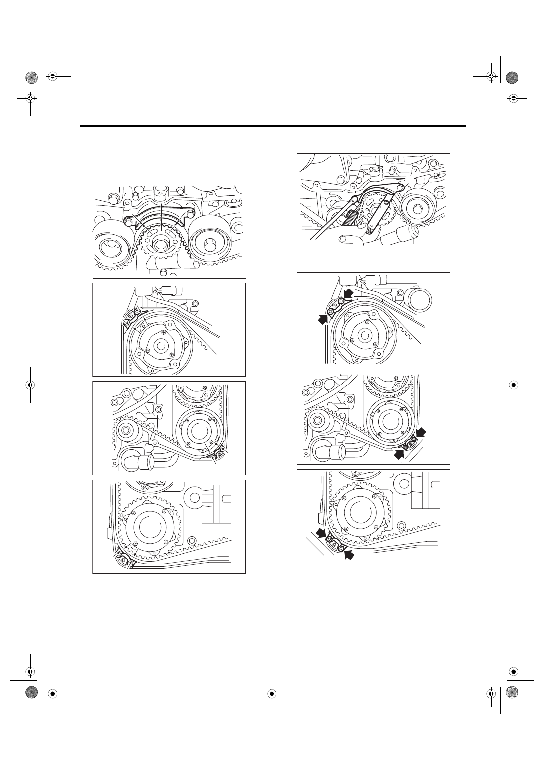
(2) Adjust the clearance between timing belt
and timing belt guide using a thickness gauge
and tighten.
Clearance:
1.0
±
0.5 mm (0.039
±
0.020 in)
Tightening torque:
9.75 N·m (1.0 kgf-m, 7.2 ft-lb)
Tightening torque:
6.4 N·m (0.7 kgf-m, 4.7 ft-lb)
12) Install the timing belt cover. <Ref. to ME(STI)-
49, INSTALLATION, Timing Belt Cover.>
13) Install the crank pulley. <Ref. to ME(STI)-47,
ME-00246
ME-03138
ME-03139
ME-03140
ME-00247
ME-03124
ME-03125
ME-03126
Нет комментариевНе стесняйтесь поделиться с нами вашим ценным мнением.
Текст