Subaru Impreza 3 / Impreza WRX / Impreza WRX STI. Service manual — part 118
SC(STI)-28
Battery
STARTING/CHARGING SYSTEMS
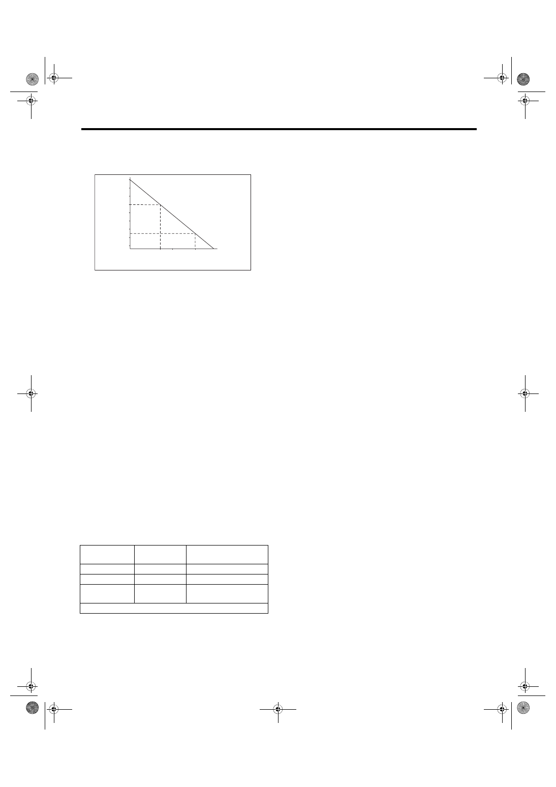
2) Measuring the specific gravity of the electrolyte
in the battery will disclose the state of charge of the
battery. The relation between specific gravity and
state of charge is as shown in the figure.
D: MEASUREMENT
WARNING:
Do not bring an open flame close to the battery
when working.
CAUTION:
• Prior to charging, corroded terminals should
be cleaned with a brush and common caustic
soda solution.
• Be careful since battery electrolyte overflows
while charging the battery.
• Observe instructions when handling the bat-
tery charger.
• Before charging the battery on the vehicle,
disconnect the battery ground terminal to pre-
vent damage of generator diodes or other elec-
trical units.
1. JUDGMENT OF BATTERY IN CHARGED
CONDITION
1) Specific gravity of electrolyte should be held
within the specific range of 1.250 — 1.290 for one
hour or more.
2) Voltage per battery cell should be held at a spe-
cific value in a range of 2.5 — 2.8 V for one hour or
more.
2. CHECK CONDITION OF CHARGE WITH
HYDROMETER
3. NORMAL CHARGING
Charge the battery at the current value specified by
manufacturer or at approximately 1/10 of battery’s
ampere-hour rating.
4. QUICK CHARGING
CAUTION:
• Observe the items in “3. NORMAL CHARG-
ING”.
• Never use 10 A or more when charging the
battery because it will shorten the battery life.
Quick charging is a method that the battery is
charged in a short period of time with a relatively
large current by using a quick charger.
Since a large current flow raises electrolyte temper-
ature, the battery is subject to damage if the large
current is used for prolonged time. For this reason,
quick charging must be carried out within a current
range that will not raise the electrolyte temperature
to 40°C (104°F) or more.
Also the quick charging is a temporary mean to
bring battery voltage up to some level, and battery
should be charged slowly with low current as a rule.
Hydrometer
indicator
State of
charge
Corrective action
Green dot
65% or more
Load test
Dark dot
65% or less
Charge battery
Clear dot
Low electrolyte
Replace the battery.*
(If cranking is difficult)
* Check electrical system before replacement.
1.28
Specific gravity [20˚C (68˚F)]
Specific gravity and state of charge
Complete charge
Charging condition
1.26
1.24
1.22
1.20
1.18
1.16
1.14
1.12
100%
75% 50%
22%
0%
(%)
SC-00094
2014 IMPREZA WRX STI SERVICE MANUAL
QUICK REFERENCE INDEX
FUJI HEAVY INDUSTRIES LTD.
G1180BE3
ENGINE 2 SECTION
This service manual has been prepared
to provide SUBARU service personnel
with the necessary information and data
for the correct maintenance and repair
of SUBARU vehicles.
This manual includes the procedures
for maintenance, disassembling, reas-
sembling, inspection and adjustment of
components and diagnostics for guid-
ance of experienced mechanics.
Please peruse and utilize this manual
fully to ensure complete repair work for
satisfying our customers by keeping
their vehicle in optimum condition.
When replacement of parts during
repair work is needed, be sure to use
SUBARU genuine parts.
All information, illustration and specifi-
cations contained in this manual are
based on the latest product information
available at the time of publication
approval.
FUEL INJECTION (FUEL SYSTEMS)
FU(w/o STI)
Page
General Description . . . . . . . . . . . . . . . . . . . . ...2
Throttle Body . . . . . . . . . . . . . . . . . . . . . . . 15
Intake Manifold . . . . . . . . . . . . . . . . . . . . . . .18
Engine Coolant Temperature Sensor . . . . . . . . . . . . . ...34
Crankshaft Position Sensor . . . . . . . . . . . . . . . . . ..35
Camshaft Position Sensor . . . . . . . . . . . . . . . . . . 37
Knock Sensor . . . . . . . . . . . . . . . . . . . . . . ...39
Throttle Position Sensor . . . . . . . . . . . . . . . . . . ...41
Mass Air Flow and Intake Air Temperature Sensor . . . . . . . . .42
Manifold Absolute Pressure Sensor . . . . . . . . . . . . . . .43
Fuel Injector . . . . . . . . . . . . . . . . . . . . . . . .45
Tumble Generator Valve Assembly . . . . . . . . . . . . . . .48
Tumble Generator Valve Actuator . . . . . . . . . . . . . . . 49
Oil Flow Control Solenoid Valve . . . . . . . . . . . . . . . ...50
Wastegate Control Solenoid Valve . . . . . . . . . . . . . . ..51
Front Oxygen (A/F) Sensor . . . . . . . . . . . . . . . . . ..53
Rear Oxygen Sensor . . . . . . . . . . . . . . . . . . . . 55
Engine Control Module (ECM) . . . . . . . . . . . . . . . . .57
Main Relay . . . . . . . . . . . . . . . . . . . . . . . ...58
Fuel Pump Relay . . . . . . . . . . . . . . . . . . . . . ..60
Electronic Throttle Control Relay . . . . . . . . . . . . . . . .62
Fuel Pump Control Unit . . . . . . . . . . . . . . . . . . . 64
Fuel . . . . . . . . . . . . . . . . . . . . . . . . . . ..65
Fuel Tank . . . . . . . . . . . . . . . . . . . . . . . . .68
Fuel Filler Pipe . . . . . . . . . . . . . . . . . . . . . . .75
Fuel Pump . . . . . . . . . . . . . . . . . . . . . . . . 78
Fuel Level Sensor . . . . . . . . . . . . . . . . . . . . . 80
Fuel Sub Level Sensor . . . . . . . . . . . . . . . . . . . .81
Fuel Filter . . . . . . . . . . . . . . . . . . . . . . . . .83
Fuel Damper . . . . . . . . . . . . . . . . . . . . . . . 87
Purge Damper . . . . . . . . . . . . . . . . . . . . . . ..88
Fuel Delivery, Return and Evaporation Lines . . . . . . . . . . ...89
Fuel System Trouble in General . . . . . . . . . . . . . . . ..94
FU(w/o STI)-2
General Description
FUEL INJECTION (FUEL SYSTEMS)
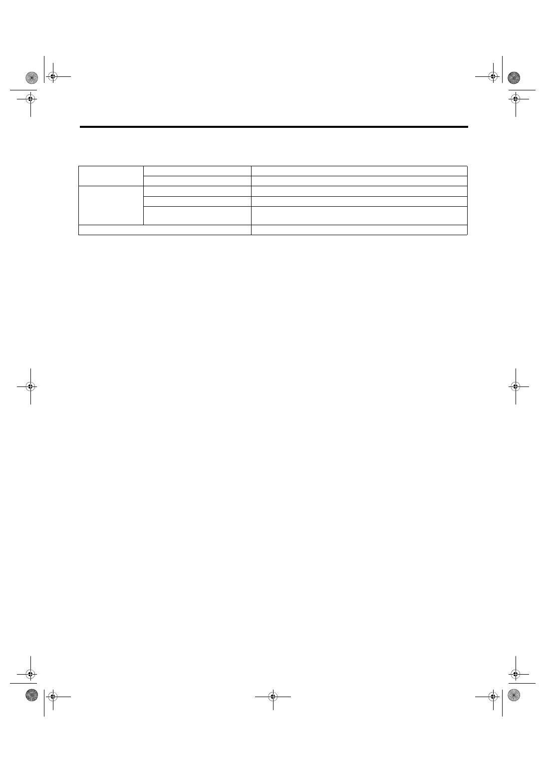
1. General Description
A: SPECIFICATION
Fuel tank
Capacity
64 L (16.9 US gal, 14.1 Imp gal)
Location
Under rear seat
Fuel pump
Type
Impeller
Shutoff discharge pressure
550 — 850 kPa (5.61 — 8.67 kgf/cm
2
, 79.8 — 123.3 psi)
Discharge rate
155 L (40.9 US gal, 34.1 Imp gal)/h or more
[12 V at 300 kPa (3.06 kgf/cm
2
, 43.5 psi)]
Fuel filter
In-tank type
Нет комментариевНе стесняйтесь поделиться с нами вашим ценным мнением.
Текст