Subaru Impreza 3 / Impreza WRX / Impreza WRX STI. Service manual — part 251
EN(H4DOTC)(diag)-228
Diagnostic Procedure with Diagnostic Trouble Code (DTC)
ENGINE (DIAGNOSTICS)
• Models with SI-DRIVE <Ref. to WI-48, WITH SI-DRIVE, WIRING DIAGRAM, Engine Electrical System.>
Step
Check
Yes
No
1
CHECK SECONDARY AIR PUMP FUSE.
Check if the secondary air pump fuse (60 A) is
blown out.
Is the fuse blown out?
EN-08735
F9
13
12
11
14
1
2
2
1
3
4
16
15
5
6
B143
F37
B144
B21
E2
E40
E41
B134
A:
A:
B135
B:
B135
B:
B137
D:
F37
F11
F9
10A
60A
9
10
8
7
11
5
20
8
B8
B20
B27
A19
D9
A29
6
1
2
8
47
3
2
1
6
4
1
2
9
2
16
18
14
12
10
4
14
4
B134
46
B220
24
23
22
21
B137
D:
31
30
29
28
27
21
20
19
18
17
16
26
25
24
15
14
13
12
11
23
22
10
3
4
9
1
2
8
7
6
5
F11
1 2
29
4
3
1
2
7
6
5
10 11 12 13 14 15
25
24
16
30
9
8
17 18 19
20
28
21 22 23
32
31
26 27
33
34 35
B220
18
19
6
7
4
3
5
2
1
12
11
10
9
8
40
36 39
38
37
34
33
35
32
28 31
30
29
23
22
21
20
26
25
24
27
17
16
15
14
13
4
3
B220
15A
16
15
8
7
4
14
13
11
12
10
9
2
1
3
6
5
B143
20
19
18
17
16
15
14
13
12
11
10
9
8
7
6
5
4
3
2
1
F37
20
19
18
17
16
15
14
13
12
11
10
9
8
7
6
5
4
3
2
1
B144
3
8
2
6
7
1
5
4
9
31
30
32
29
34
33
21
20
19
18
17
16
28
27
26
15
14
13
12
11
25
23
22
24
10
3
4
9
1
2
8
7
6
5
E40
2
6
5
4
3
1
E41
2
1
54
52 53
50 51
48 49
46 47
45
44
42 43
40 41
38 39
36 37
34 35
33
32
31
30
29
28
27
26
25
24
23
22
21
20
11
10
9
19
18
17
16
8
7
6
5
15
14
13
12
4
3
2
1
B21
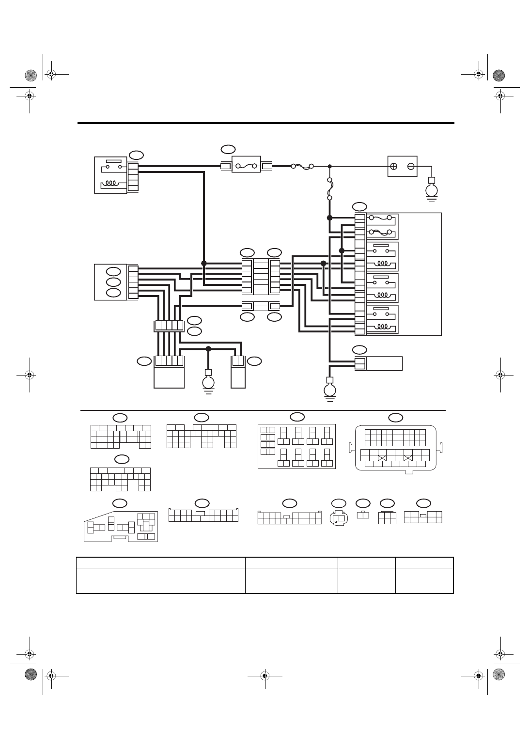
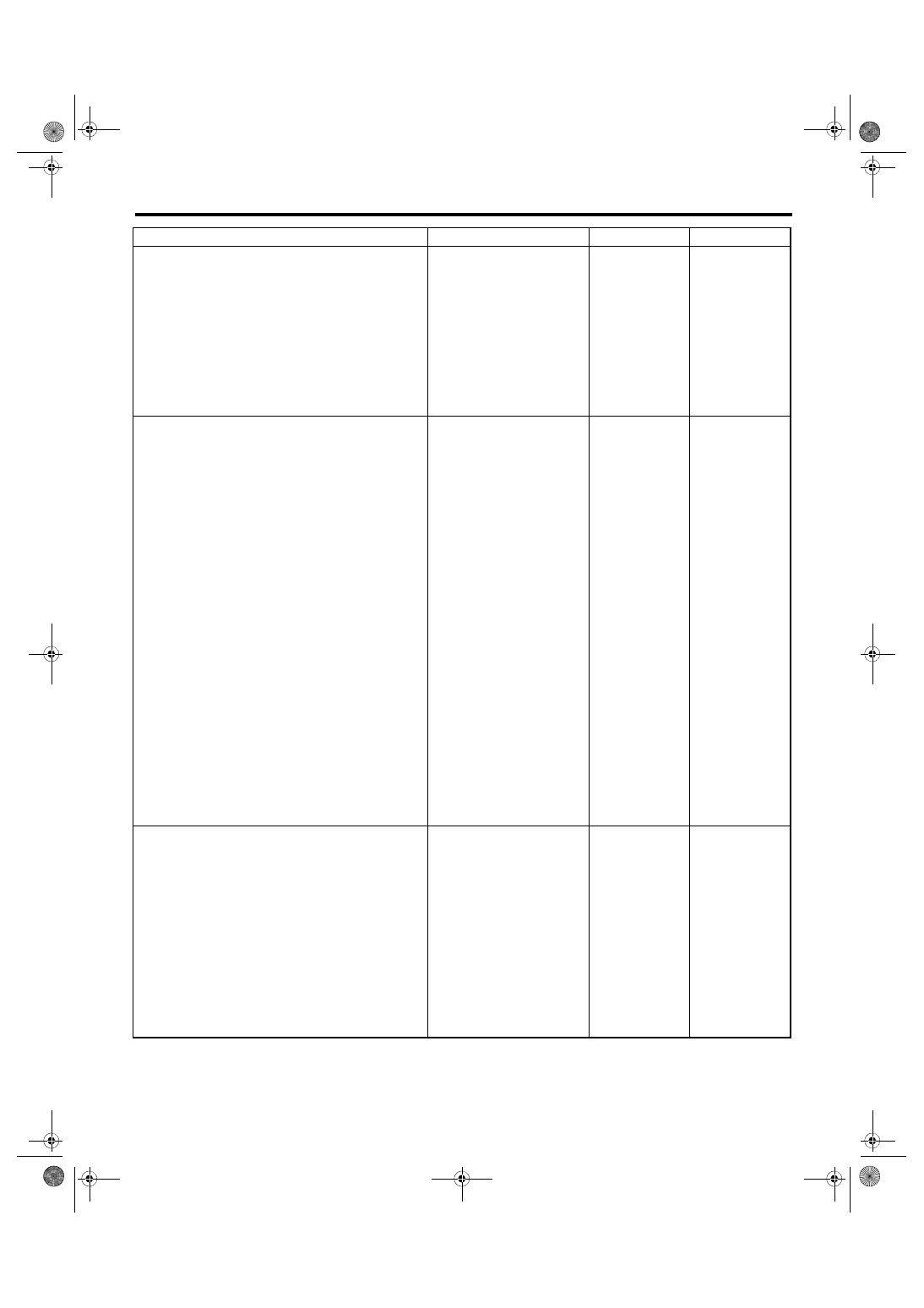
E
E
E
ECM
SBF-7
FUSE
(RELAY BLOCK)
MAIN SBF
MAIN RELAY
SECONDARY
AIR COMBINATION
VALVE RELAY 2
SECONDARY
AIR PUMP
RELAY
SECONDARY
AIR COMBINATION
VALVE RH
SECONDARY
AIR COMBINATION
VALVE LH
(WITH BUILT-IN
PRESSURE SENSOR)
SECONDARY
AIR COMBINATION
VALVE RELAY 1
SECONDARY
AIR PUMP
MAIN FUSE BOX
(M/B)
RELAY HOLDER
BATTERY
EN(H4DOTC)(diag)-229
Diagnostic Procedure with Diagnostic Trouble Code (DTC)
ENGINE (DIAGNOSTICS)
2
CHECK HARNESS BETWEEN FUSE BOX
AND SECONDARY AIR PUMP CONNECTOR.
1) Remove the secondary air pump fuse from
the fuse box.
2) Disconnect the secondary air pump connec-
tor.
3) Measure the resistance between the sec-
ondary air pump fuse and secondary air pump
connector, and chassis ground.
Connector & terminal
(F9) No. 16 — Chassis ground:
(F11) No. 2 — Chassis ground:
Is the resistance 1 MΩ or
more?
Replace the fuse
with a new part,
and connect the
secondary air
pump connector.
Go to step
Repair ground
short of the har-
ness between the
fuse box and the
secondary air
pump connector.
3
CHECK SECONDARY AIR PUMP OPERA-
TION.
CAUTION:
Try your best to complete the confirmation
process of this inspection in one try. This in-
spection will put a heavy workload on the
secondary air pump, so the continuous op-
eration may cause damage to the pump. Do
not operate the pump continuously for more
than three times. If you need to operate the
pump further, turn the ignition switch to
OFF and wait for at least two hours.
1) Connect the delivery (test) mode connector.
2) Turn the ignition switch to ON.
3) Perform operation check for the secondary
air pump using the Subaru Select Monitor.
NOTE:
• The compulsory operation using the Subaru
Select Monitor is performed only for 10 seconds
in order to protect the secondary air pump.
When you want to operate the pump again, dis-
connect the ground cable from battery, wait at
least one minute, and perform the clear memo-
ry operation of ECM. Then, perform the forced
operation using the Subaru Select Monitor.
• Refer to “Compulsory Valve Operation Check
Mode” for detailed procedures. <Ref. to
EN(H4DOTC)(diag)-64, Compulsory Valve Op-
eration Check Mode.>
Does the secondary air pump
operate?
4
CHECK DUCT BETWEEN SECONDARY AIR
PUMP AND COMBINATION VALVE.
Check the duct between secondary air pump
and combination valve.
Is there damage, clog or dis-
connection of the duct?
Replace, clean or
connect the duct.
Step
Check
Yes
No
EN(H4DOTC)(diag)-230
Diagnostic Procedure with Diagnostic Trouble Code (DTC)
ENGINE (DIAGNOSTICS)
5
CHECK POWER SUPPLY TO SECONDARY
AIR PUMP.
1) Turn the ignition switch to OFF.
2) Disconnect the battery negative terminal,
wait for 1 minute, and connect it again.
3) Disconnect the secondary air pump connec-
tor.
4) Connect the delivery (test) mode connector.
5) Turn the ignition switch to ON.
6) Using the Subaru Select Monitor, measure
the voltage between the secondary air pump
connector and chassis ground while the sec-
ondary air pump is operating.
NOTE:
• The compulsory operation using the Subaru
Select Monitor is performed only for 10 seconds
in order to protect the secondary air pump.
When you want to operate the pump again, dis-
connect the ground cable from battery, wait at
least one minute, and perform the clear memo-
ry operation of ECM. Then, perform the forced
operation using the Subaru Select Monitor.
• Refer to “Compulsory Valve Operation Check
Mode” for detailed procedures. <Ref. to
EN(H4DOTC)(diag)-64, Compulsory Valve Op-
eration Check Mode.>
Connector & terminal
(F11) No. 2 (+) — Chassis ground (–):
Is the voltage 10 V or more?
6
CHECK HARNESS BETWEEN SECONDARY
AIR PUMP RELAY AND SECONDARY AIR
PUMP CONNECTOR.
1) Turn the ignition switch to OFF.
2) Remove the secondary air pump relay.
3) Measure the resistance of harness between
secondary air pump relay connector and sec-
ondary air pump connector.
Connector & terminal
(F9) No. 11 — (F11) No. 2:
Is the resistance less than 1 Ω? Go to step
Repair the open
circuit in harness
between second-
ary air pump relay
connector and sec-
ondary air pump
connector.
7
CHECK HARNESS BETWEEN SECONDARY
AIR PUMP CONNECTOR AND CHASSIS
GROUND.
Measure the resistance of the harness between
secondary air pump connector and chassis
ground.
Connector & terminal
(F11) No. 1 — Chassis ground:
Is the resistance less than 5 Ω? Go to step
Repair the open
circuit of the har-
ness between sec-
ondary air pump
connector and
chassis ground.
8
CHECK SECONDARY AIR PUMP RELAY.
1) Connect the battery to terminals No. 12 and
No. 13 of the secondary air pump relay.
2) Measure the resistance between secondary
air pump relay terminals.
Terminals
No. 14 — No. 11:
Is the resistance less than 1 Ω? Go to step
Step
Check
Yes
No
EN(H4DOTC)(diag)-231
Diagnostic Procedure with Diagnostic Trouble Code (DTC)
ENGINE (DIAGNOSTICS)
9
CHECK SECONDARY AIR PUMP RELAY
POWER SUPPLY.
1) Turn the ignition switch to ON.
2) Measure the voltage between the second-
ary air pump relay connector and chassis
ground.
Connector & terminal
(F9) No. 14 (+) — Chassis ground (–):
(F9) No. 12 (+) — Chassis ground (–):
Is the voltage 10 V or more?
Repair the open or
ground short circuit
of power supply
circuit.
10
CHECK HARNESS BETWEEN ECM AND
SECONDARY AIR PUMP RELAY CONNEC-
TOR.
1) Turn the ignition switch to OFF.
2) Disconnect the ECM connector.
3) Measure the resistance of harness between
ECM connector and secondary air pump relay
connector.
Connector & terminal
(B135) No. 27 — (F9) No. 13:
Is the resistance less than 1 Ω? Repair the poor
contact of ECM
connector.
Repair the harness
and connector.
NOTE:
In this case, repair
the following item:
• Open circuit in
harness between
ECM
connector
and secondary air
pump relay con-
nector
• Poor contact of
coupling connector
Step
Check
Yes
No
Нет комментариевНе стесняйтесь поделиться с нами вашим ценным мнением.
Текст