Subaru Impreza 3 / Impreza WRX / Impreza WRX STI. Service manual — part 535
VDC(diag)-39
Warning Light Illumination Pattern
VEHICLE DYNAMICS CONTROL (VDC) (DIAGNOSTICS)
K: BRAKE WARNING LIGHT DOES NOT GO OFF
DETECTING CONDITION:
• Brake warning light circuit is shorted.
• Defective sensor/connector
• Defective CAN communication
TROUBLE SYMPTOM:
After starting the engine, the brake warning light remains lit though the parking lever is released.
VDC(diag)-40
Warning Light Illumination Pattern
VEHICLE DYNAMICS CONTROL (VDC) (DIAGNOSTICS)
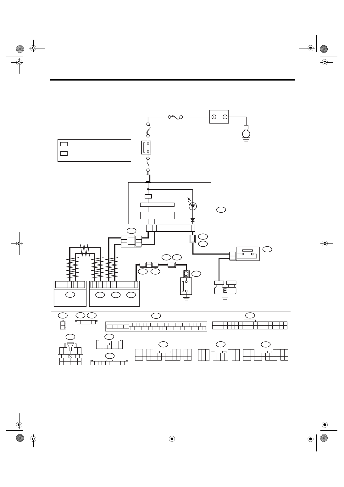
WIRING DIAGRAM:
5
2
46
45
44
43
42
41
40
39
38
37
36
35
34
33
32
31
30
29
28
27
26
25
24
23
22
21
20
19
18
17
16
15
14
13
12
11
i77
1 2 3 4 5 6 7 8 9 10
i77
*
2
*
2
*
1
*
1
*
2
*
1
3
3
B438
B437
1 2 3 4 5
R3
R4
B437
B438
B99
10
B99
1 2
3 4 5
6 7 8 9 10 11 12
1 2 3 4 5 6 7 8 9 10 11 12 13 14 15 16 17 18 19 20
21 22 23 24 25 26 27 28 29 30 31 32 33 34 35 36 37 38 39 40
C: B281
5 6 7
8
2
1
9
4
3
10
24
22 23
25
11 12 13 14 15
26
27 28
16 17 18 19
20 21
B: B280
1 2 3
4 5 6
7 8 9 10 11 12 13 14 15 16 17
18 19 20
21 22 23 24
25 26
A:
i84
1 2
3 4
5 6
7 8
9 10 11 12
14 15 16 17 18 19 20 21 22 23
24 25
26 27 28 29
30 31 32 33
34 35
13
1
2
C: B281
B: B280
A:
i84
2
1
24
8
26
27
C15
A9
A1
B9
B3
i10
i3
B16
B38
B310
10
35
i10
9
8
7
6
5
4
3
2
1
27 28
26
21 22
20
24 25
23
18 19
17
12 13
14 15
11
16
5 6 7 8 9 10
4
3
2
1
B16
i3
B310
VDC01085
E
SBF-6
I/F
MAIN SBF
No.
5
BODY INTEGRATED UNIT
BATTERY
COMBINATION
METER
MICRO COMPUTER
CAN TRANSCEIVER &
RECEIVER
BRAKE FLUID
LEVEL SWITCH
PARKING BRAKE/
BRAKE FLUID LEVEL
W
ARNING LIGHT
IGNITION
SWITCH
PARKING
BRAKE
SWITCH
: TERMINAL No. OPTIONAL
ARRANGEMENT AMONG 1, 2, 3, 4 AND 5
: TERMINAL No. OPTIONAL
ARRANGEMENT AMONG 6, 7, 8, 9 AND 10
VDCCM & H/U
VDC(diag)-41
Warning Light Illumination Pattern
VEHICLE DYNAMICS CONTROL (VDC) (DIAGNOSTICS)
Step
Check
Yes
No
1
CHECK INSTALLATION OF VDCCM&H/U
CONNECTOR.
1) Turn the ignition switch to OFF.
2) Check that the VDCCM&H/U connector is
inserted until it is locked by clamp.
Is the connector firmly
inserted?
Insert the
VDCCM&H/U con-
nector until it is
locked by clamp.
2
READ DTC.
Read the DTC. <Ref. to VDC(diag)-25, Read
Diagnostic Trouble Code (DTC).>
Is DTC displayed?
3
CHECK BRAKE FLUID AMOUNT.
Check the amount of brake fluid in the reservoir
tank of master cylinder.
Does the level of the brake fluid
amount fall between the lines of
“MAX” and “MIN”?
Replenish brake
fluid to the speci-
fied value.
4
CHECK BRAKE FLUID LEVEL SWITCH.
1) Turn the ignition switch to OFF.
2) Disconnect the level switch connector (B16)
from master cylinder.
3) Measure the resistance of master cylinder
terminals.
Terminals
No. 1 — No. 2:
Is the resistance 1 MΩ or
more?
Replace the mas-
ter cylinder. <Ref.
to BR-33, Master
Cylinder.>
5
CHECK GROUND SHORT OF HARNESS.
1) Disconnect the connector (i10) from combi-
nation meter.
2) Measure the resistance between combina-
tion meter connector and chassis ground.
Connector & terminal
(i10) No. 8 — Chassis ground:
Is the resistance 1 MΩ or
more?
Repair the harness
between combina-
tion meter and
brake fluid level
switch.
6
CHECK PARKING BRAKE SWITCH.
1) Disconnect the connector (R4) from parking
brake switch.
2) Release the parking brake.
3) Measure the resistance between parking
brake switch terminal and chassis ground.
Is the resistance 1 MΩ or
more?
Replace the park-
ing brake switch.
7
CHECK GROUND SHORT OF HARNESS.
1) Disconnect the connector (B281) from body
integrated unit.
2) Measure the resistance between body inte-
grated unit connector and chassis ground.
Connector & terminal
(B281) No. 15 — Chassis ground:
Is the resistance 1 MΩ or
more?
Repair the harness
between body inte-
grated unit and
parking brake
switch.
8
CHECK POOR CONTACT OF CONNECTOR.
Check for poor contact of all connectors.
Is there poor contact?
Repair the connec-
tor.
9
CHECK LAN SYSTEM.
Perform the diagnosis for LAN system. <Ref. to
LAN(diag)-2, Basic Diagnostic Procedure.>
Is there any fault in LAN sys-
tem?
10
CHECK COMBINATION METER.
Check the combination meter. <Ref. to IDI-5,
INSPECTION, Combination Meter System.>
Is combination meter OK?
Replace the com-
bination meter.
<Ref. to IDI-16,
Combination
Meter.>
VDC(diag)-42
Warning Light Illumination Pattern
VEHICLE DYNAMICS CONTROL (VDC) (DIAGNOSTICS)
L: VDC MODE DOES NOT CHANGE
1. VDC TRACTION MODE
NOTE:
This diagnosis is applied to 6MT model.
DETECTING CONDITION
• Defective combination meter
• Defective CAN communication
• Defective VDC OFF switch
TROUBLE SYMPTOM:
Even when the VDC OFF switch is operated, the VDC traction mode indicator light does not illuminate, or the
illumination color does not change. (The VDC mode does not change)
NOTE:
• When the VDC OFF switch is pressed (2 seconds or less), the VDC traction mode indicator light illumi-
nates in green. (Traction mode)
• When the VDC OFF switch is held down (2 seconds or more, 10 seconds or less), the VDC OFF indicator
light illuminates in yellow. (VDC OFF mode)
• When the VDC OFF switch is pressed for 10 seconds or more, the VDC traction mode indicator light goes
off, and subsequent switch operations are not accepted. When turning the ignition switch from OFF to ON,
the OFF operation enabled status is restored.
Нет комментариевНе стесняйтесь поделиться с нами вашим ценным мнением.
Текст