Subaru Impreza 3 / Impreza WRX / Impreza WRX STI. Service manual — part 513
DS-25
Rear Hub Unit Bearing
DRIVE SHAFT SYSTEM
B: INSTALLATION
1) Aligning with the mounting hole of the rear brake
back plate, temporarily tighten the rear hub unit
bearing to the rear housing.
CAUTION:
• Be careful not to damage the magnetic en-
coder.
• Do not get closer the tool which charged
magnetism to magnetic encoder.
2) Tighten the four bolts of the rear housing.
Tightening torque:
65 N·m (6.63 kgf-m, 47.9 ft-lb)
3) Tighten the new axle nut temporarily.
4) Install the rear disc rotor.
5) Install the disc brake caliper on the rear housing.
Tightening torque:
17-inch type
65 N·m (6.63 kgf-m, 47.9 ft-lb)
15-inch type
66 N·m (6.73 kgf-m, 48.7 ft-lb)
6) While pressing the brake pedal, tighten the new
axle nuts to the specified torque.
Tightening torque:
190 N·m (19.4 kgf-m, 140.1 ft-lb)
CAUTION:
Do not apply weight to the rear axle before
tightening the axle nut. Doing so may damage
the hub bearing.
7) After tightening the axle nut, lock it securely.
8) Install the rear wheels.
Tightening torque:
100 N·m (10.20 kgf-m, 73.8 ft-lb)
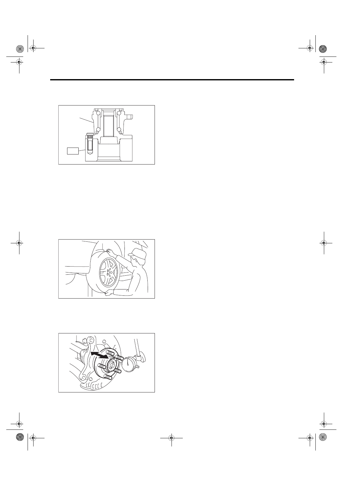
C: DISASSEMBLY
Using the ST and a hydraulic press, push out the
hub bolts.
CAUTION:
• Be careful not to hammer the hub bolts. This
may deform the hub.
• Do not reuse the hub bolt.
ST 28399AG000 HUB STAND
NOTE:
Since the hub unit bearing can not be disassem-
bled, only hub bolts can be removed.
(1) Magnetic encoder
(2) Rear hub unit bearing
DS-00251
(2)
(1)
DS-00414
(1) Rear hub unit bearing
DS-00048
DS-00254
ST
(1)
DS-26
Rear Hub Unit Bearing
DRIVE SHAFT SYSTEM
D: ASSEMBLY
1) Attach the hub to the ST securely.
ST 28099PA080 HUB STAND
2) Using a press, press the new hub bolts until their
seating surfaces contact the hub.
NOTE:
Use the 12 mm (0.47 in) dia. holes in the HUB
STAND to prevent bolts from tilting.
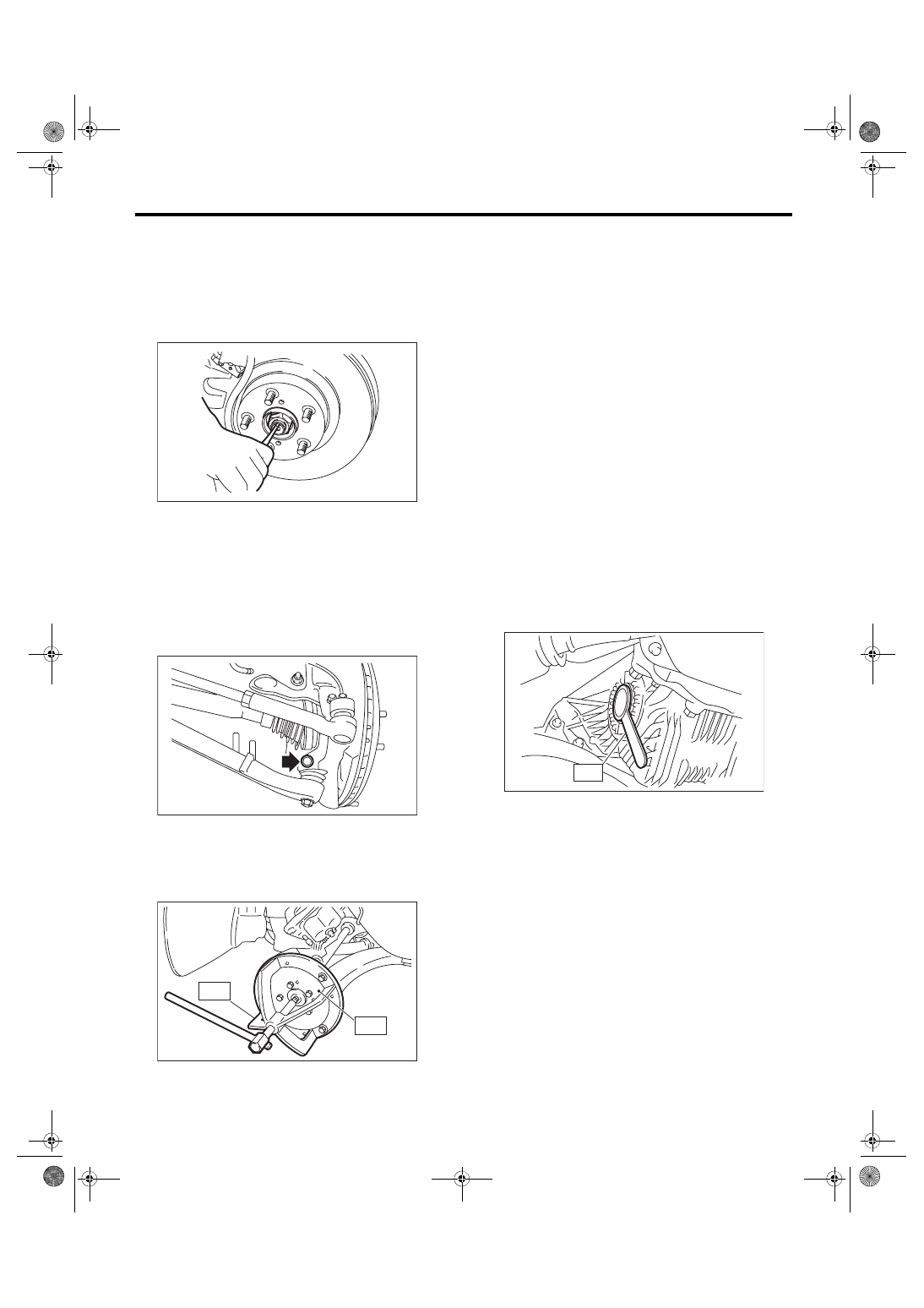
E: INSPECTION
1) Moving the rear tire up and down by hand, check
there is no backlash in bearing, and check the
wheel rotates smoothly.
2) Inspect the lean of axis direction using a dial
gauge. Replace the hub bearing if the play exceeds
the limit value.
Service limit:
Maximum: 0.05 mm (0.0020 in)
(1) Rear hub unit bearing
DS-00255
ST
(1)
DS-00183
DS-00062
DS-27
Front Drive Shaft
DRIVE SHAFT SYSTEM
7. Front Drive Shaft
A: REMOVAL
1) Disconnect the ground cable from battery.
2) Lift up the vehicle, and then remove the front
wheels.
3) Lift the crimped section of axle nut.
4) Remove the axle nut using a socket wrench
while depressing the brake pedal.
CAUTION:
Do not loosen the axle nut while the front axle is
loaded. Doing so may damage the hub bearing.
5) Drain the transmission gear oil.
6) Remove the stabilizer link from front arm.
7) Disconnect the front arm ball joint from the hous-
ing.
8) Remove the front drive shaft assembly. If it is
hard to remove, use ST1 and ST2.
ST1 926470000
AXLE SHAFT PULLER
ST2 28099PA110
AXLE SHAFT PULLER
PLATE
9) Using a bar, remove the front drive shaft from
transmission.
CAUTION:
Be careful not to allow the bar to damage holder
area.
B: INSTALLATION
1) Replace the differential side retainer oil seal with
a new part.
NOTE:
After pulling out the drive shaft, be sure to replace
with a new oil seal.
6MT model: <Ref. to 6MT-28, REPLACEMENT,
Differential Side Retainer Oil Seal.>
5MT model: <Ref. to 5MT-32, REPLACEMENT,
Differential Side Retainer Oil Seal.>
2) Insert the AC into hub splines.
3) Draw the drive shaft into specified position.
CAUTION:
Do not hammer drive shaft when installing it.
4) Tighten the axle nut temporarily.
5) Using the ST, install the front drive shaft to trans-
mission.
ST 28399SA010 OIL SEAL PROTECTOR
6) Connect the front arm ball joint to the housing.
Tightening torque:
50 N·m (5.10 kgf-m, 36.9 ft-lb)
7) Install the stabilizer link.
CAUTION:
Use a new flange nut.
Tightening torque:
38 N·m (3.87 kgf-m, 28 ft-lb)
8) While pressing the brake pedal, tighten the new
axle nuts to the specified torque.
CAUTION:
Do not apply weight to the front axle before
tightening the axle nut. Doing so may damage
the hub bearing.
Tightening torque:
220 N·m (22.43 kgf-m, 162.3 ft-lb)
9) After tightening axle nut, lock it securely.
DS-00038
FS-00106
DS-00145
ST2
ST1
AT-00110
ST
DS-28
Front Drive Shaft
DRIVE SHAFT SYSTEM
10) Fill transmission gear oil.
11) Install the front wheels.
Tightening torque:
100 N·m (10.20 kgf-m, 73.8 ft-lb)
12) Connect the battery ground terminal.
13) Inspect the wheel alignment and adjust if nec-
essary.
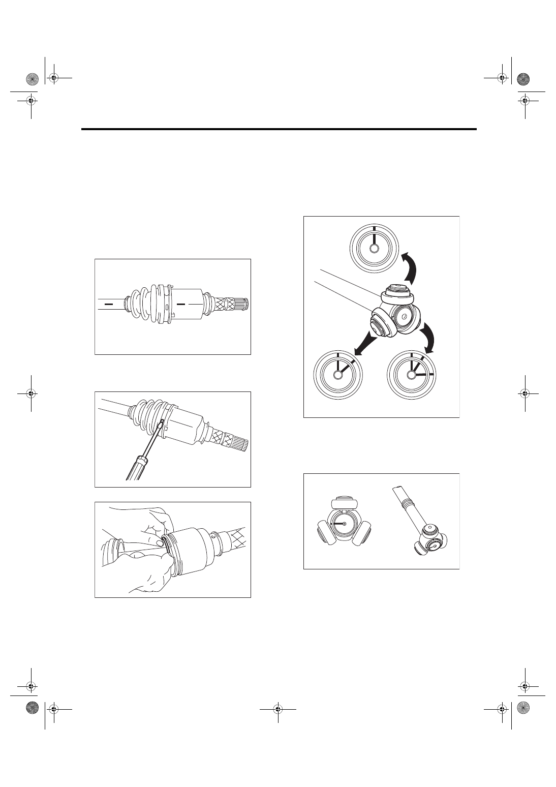
C: DISASSEMBLY
1. EXCEPT FOR STI MODEL
1) Place alignment marks on the shaft and outer
race.
2) Remove the PTJ boot band and boot.
CAUTION:
Be careful not to damage the boot.
3) Remove the snap ring from PTJ outer race.
4) Remove the PTJ outer race from shaft assem-
bly.
5) Wipe off grease.
CAUTION:
The grease is a special type of grease. Do not
mix with other grease.
6) Place alignment marks on the roller kit and trun-
nion.
7) Remove the roller kit from trunnion.
CAUTION:
Be careful with the roller kit position.
8) Place alignment marks on the trunnion and
shaft.
DS-00106
DS-00107
DS-00108
DS-00109
DS-00110
Нет комментариевНе стесняйтесь поделиться с нами вашим ценным мнением.
Текст