Subaru Legacy (2005 year). Service manual — part 39
FU(H4SO 2.0)-15
FUEL INJECTION (FUEL SYSTEM)
Intake Manifold
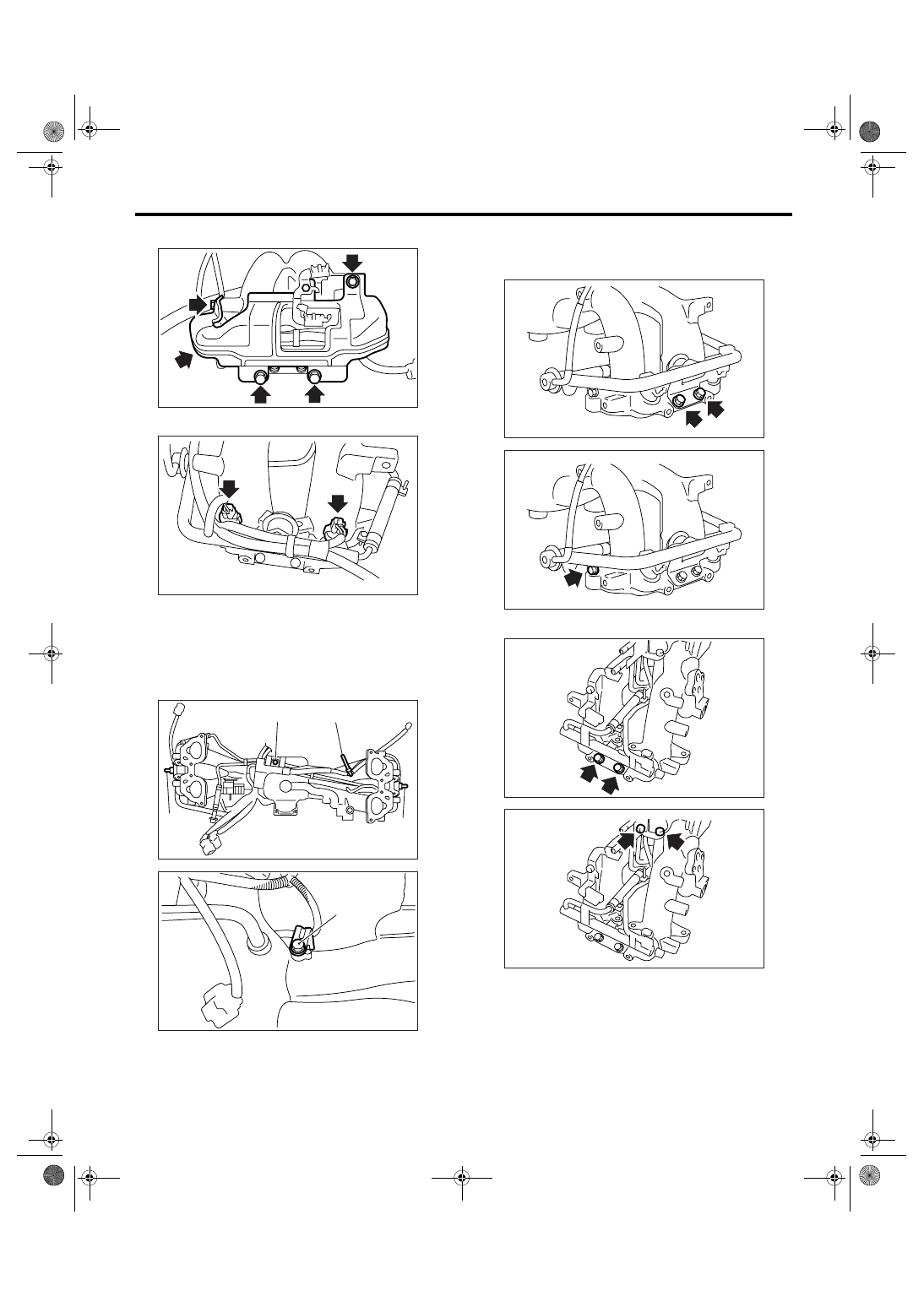
7) Remove the fuel pipe protector RH.
8) Disconnect the connector from fuel injector.
9) Remove the purge control solenoid valve. <Ref.
to EC(H4SO 2.0)-7, REMOVAL, Purge Control So-
lenoid Valve.>
10) Remove the harness band (A) and bolts (B),
(C) which secure engine harness to intake mani-
fold.
11) Remove the engine harness from intake mani-
fold.
12) Remove the bolts which install injector pipe on
the intake manifold as shown in the figure.
• RH Side
• LH Side
FU-02066
FU-02067
FU-02068
(A)
(A)
(A)
(B)
FU-02069
(C)
FU-02070
FU-02071
FU-02072
FU-02073
FU(H4SO 2.0)-16
FUEL INJECTION (FUEL SYSTEM)
Intake Manifold
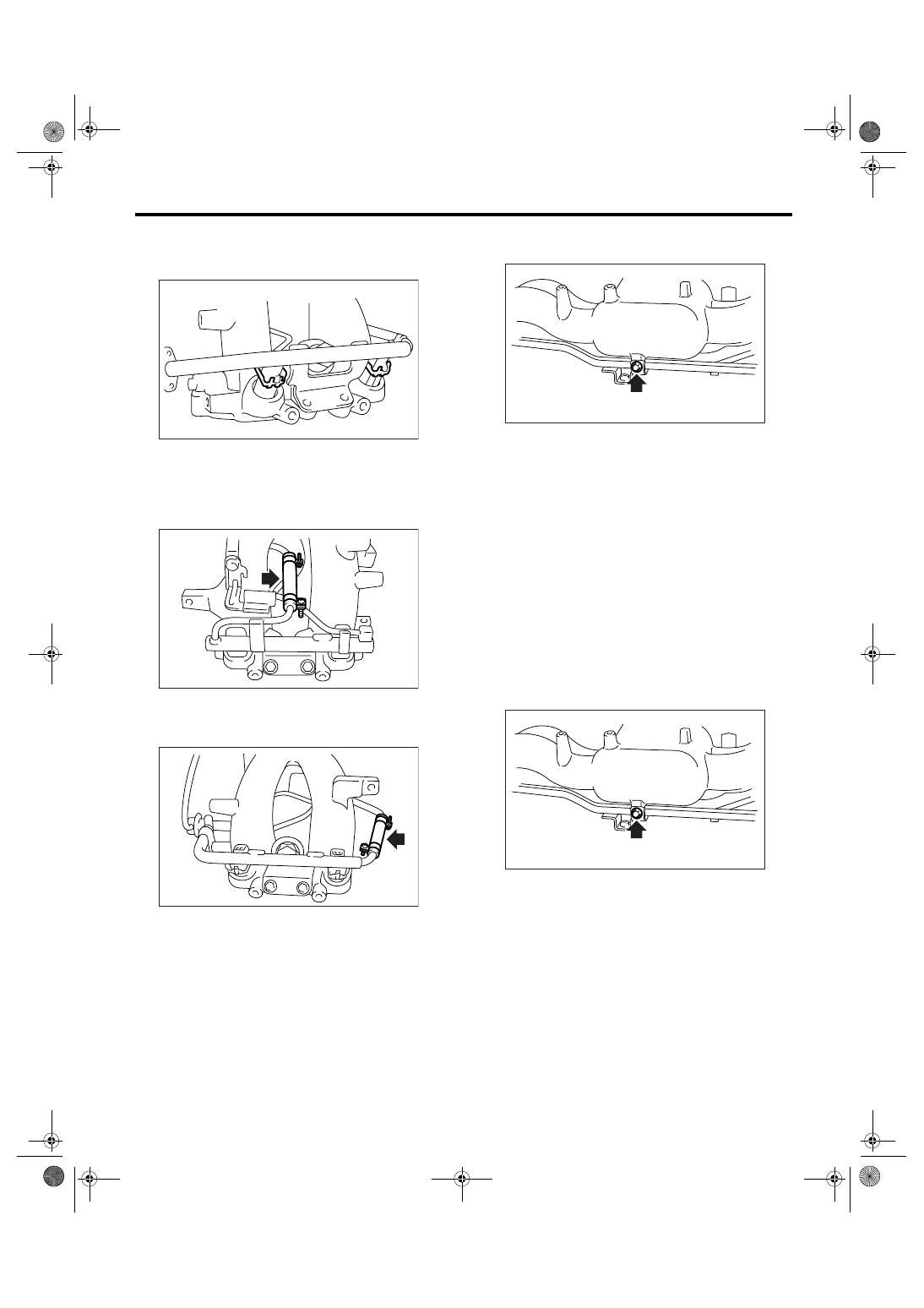
13) Remove the fuel injectors.
(1) Remove the clip which secures fuel injector
from injector pipe.
(2) Remove the fuel injector while lifting up the
fuel injector pipe.
14) Loosen the clamp which holds fuel injector pipe
LH to fuel hose, and then disconnect the pipe from
fuel hose.
15) Loosen the clamp which holds fuel injector pipe
RH to fuel hose, and then disconnect the pipe from
fuel hose.
16) Remove the fuel injector pipe.
17) Remove the bolt which installs fuel pipes on in-
take manifold.
18) Remove the fuel pipe assembly and pressure
regulator from intake manifold.
D: ASSEMBLY
NOTE:
When assembling the nipple, apply liquid gasket.
Liquid gasket:
THREE BOND 1105 (Part No. 004403010)
Tightening torque:
17 N
⋅
m (1.7 kgf-m, 12.5 ft-lb)
1) Install the fuel pipe assembly and pressure reg-
ulator to intake manifold.
2) Tighten the bolt which installs fuel pipes on in-
take manifold.
Tightening torque:
6.4 N
⋅
m (0.65 kgf-m, 4.7 ft-lb)
FU-02074
FU-02075
FU-02076
FU-02077
FU-02077
FU(H4SO 2.0)-17
FUEL INJECTION (FUEL SYSTEM)
Intake Manifold
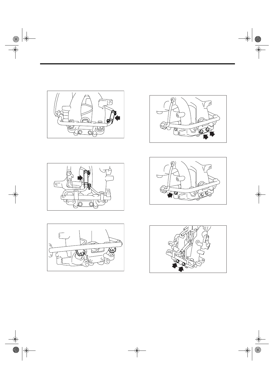
3) Connect the fuel injector pipe RH to fuel hose,
and tighten the clamp.
Tightening torque:
1.25 N
⋅
m (0.13 kgf-m, 0.94 ft-lb)
4) Connect the fuel injector pipe LH to fuel hose,
and tighten the clamp.
Tightening torque:
1.25 N
⋅
m (0.13 kgf-m, 0.94 ft-lb)
5) Install the fuel injectors.
6) Install the clip which secures fuel injector.
7) Tighten the bolts which install injector pipe on in-
take manifold.
• RH Side
Tightening torque:
19 N
⋅
m (1.9 kgf-m, 14 ft-lb)
Tightening torque:
6.4 N
⋅
m (0.65 kgf-m, 4.7 ft-lb)
• LH Side
Tightening torque:
19 N
⋅
m (1.9 kgf-m, 14 ft-lb)
FU-02076
FU-02075
FU-02074
FU-02070
FU-02071
FU-02072
FU(H4SO 2.0)-18
FUEL INJECTION (FUEL SYSTEM)
Intake Manifold
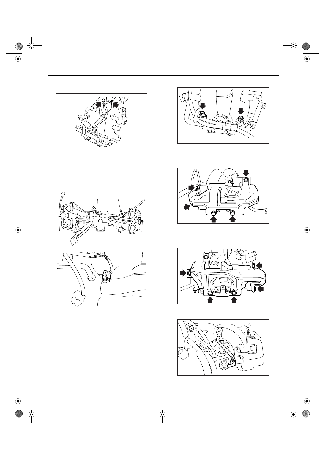
Tightening torque:
6.4 N
⋅
m (0.65 kgf-m, 4.7 ft-lb)
8) Install the engine harness to intake manifold.
9) Hold the engine harness by harness band (A)
and bolts (B), (C).
Tightening torque:
(B): 16 N
⋅
m (0.6 kgf-m, 11.8 ft-lb)
(C): 6.4 N
⋅
m (0.65 kgf-m, 4.7 ft-lb)
10) Install the purge control solenoid valve. <Ref.
to EC(H4SO 2.0)-7, INSTALLATION, Purge Con-
trol Solenoid Valve.>
11) Connect the connectors to fuel injector.
12) Install the fuel pipe protector RH.
Tightening torque:
19 N
⋅
m (1.9 kgf-m, 14 ft-lb)
13) Install the fuel pipe protector LH.
Tightening torque:
19 N
⋅
m (1.9 kgf-m, 14 ft-lb)
14) Connect the pressure regulator vacuum hose
to intake manifold.
FU-02073
FU-02068
(A)
(A)
(A)
(B)
FU-02069
(C)
FU-02067
FU-02066
FU-02065
FU-02064
Нет комментариевНе стесняйтесь поделиться с нами вашим ценным мнением.
Текст