Subaru Legacy (2005 year). Service manual — part 37
FU(H4SO 2.0)-7
FUEL INJECTION (FUEL SYSTEM)
General Description
(1)
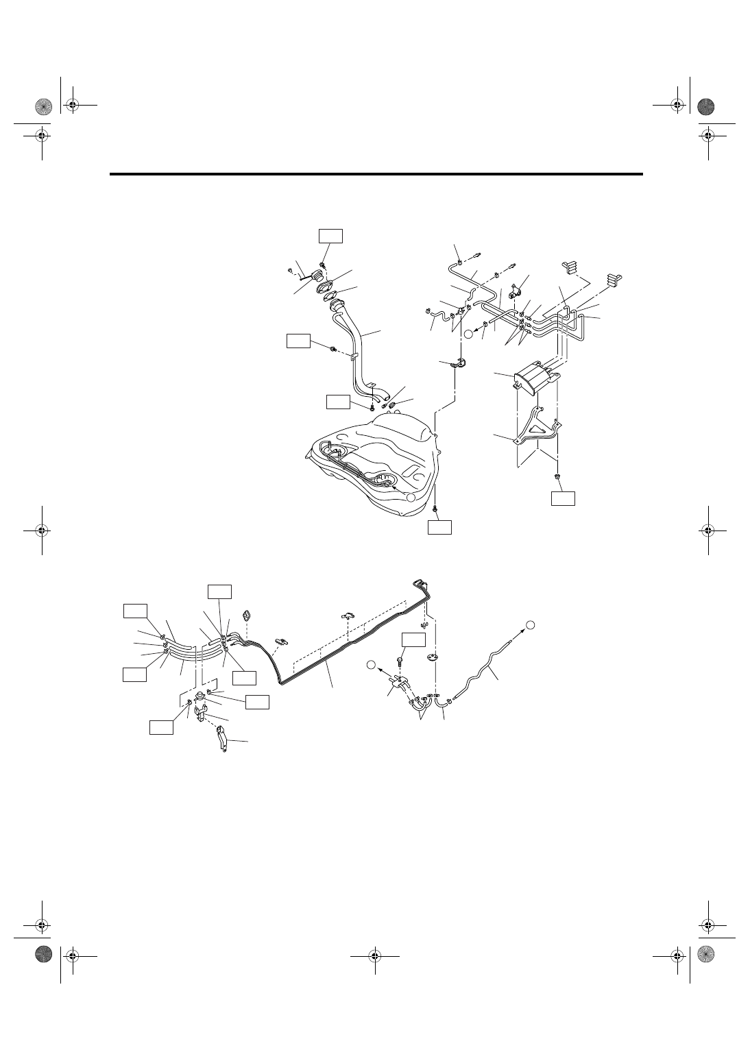
Fuel tank
(12)
Fuel sub level sensor upper plate
(23)
Heat shield cover
(2)
Fuel tank band RH
(13)
Fuel sub level sensor gasket
(24)
Fuel tank protector RH (Front)
(3)
Fuel tank band LH
(14)
Fuel filler hose
(25)
Fuel tank protector LH (Front)
(4)
Delivery tube
(15)
Clamp
(5)
Return tube
(16)
Vent hose
Tightening torque: N
⋅
m (kgf-m, ft-lb)
(6)
Jet pump tube
(17)
Clip
T1: 4.4 (0.45, 3.2)
(7)
Fuel pump ASSY
(18)
Fuel tank protector RH (Rear)
T2: 9 (0.9, 6.6)
(8)
Fuel pump upper plate
(19)
Fuel tank protector LH (Rear)
T3: 17.5 (1.78, 12.9)
(9)
Fuel pump gasket
(20)
Stopper RH
T4: 33 (3.4, 24.3)
(10)
Fuel level sensor
(21)
Stopper LH
(11)
Fuel sub level sensor
(22)
Retainer
FU(H4SO 2.0)-8
FUEL INJECTION (FUEL SYSTEM)
General Description
5. FUEL LINE
FU-02591
(1)
(35)
(35)
(35)
(9)
(32)
(30)
(31)
(11)
(15)
(1)
(1)
(16)
(1)
(20)
(19)
(14)
(13)
(12)
(1)
(22)
(22)
(10)
(29)
(17)
(26)
(25)
(24)
(18)
(23)
(1)
(21)
(34)
(28)
(27)
T3
T2
T4
T3
T3
T3
(33)
B
A
A
B
(1)
(3)
(2)
(4)
(5)
(6)
(7)
(8)
T1
(35)
T1
T1
T1
(35)
(35)
T1
T1
FU(H4SO 2.0)-9
FUEL INJECTION (FUEL SYSTEM)
General Description
C: CAUTION
• Wear work clothing, including a cap, protective
goggles, and protective shoes during operation.
• Remove contamination including dirt and corro-
sion before removal, installation or disassembly.
• Keep the disassembled parts in order and pro-
tect them from dust and dirt.
• Before removal, installation or disassembly, be
sure to clarify the failure. Avoid unnecessary re-
moval, installation, disassembly and replacement.
• Be careful not to burn yourself, because each
part on the vehicle is hot after running.
• Be sure to tighten fasteners including bolts and
nuts to the specified torque.
• Place shop jacks or rigid racks at the specified
points.
• Before disconnecting connectors of sensors or
units, be sure to disconnect the ground cable from
battery.
• Place “NO FIRE” signs near the working area.
• Be careful not to spill fuel on the floor.
D: PREPARATION TOOL
(1)
Clip
(15)
Purge hose A
(29)
Clip
(2)
Fuel return hose
(16)
Purge hose B
(30)
Fuel hose
(3)
Evaporation hose A
(17)
Two-way valve hose B
(31)
Purge hose C
(4)
Fuel delivery hose A
(18)
Canister drain hose B
(32)
Connector
(5)
Fuel delivery hose B
(19)
Two-way valve drain hose
(33)
Purge pipe
(6)
Fuel damper
(20)
Two-way valve
(34)
Two-way valve bracket
(7)
Fuel damper holder
(21)
Two-way valve hose C
(35)
Clamp
(8)
Fuel damper bracket
(22)
Connector
(9)
Fuel pipe ASSY
(23)
Evaporation hose holder
Tightening torque: N
⋅
m (kgf-m, ft-lb)
(10)
Clamp
(24)
Fuel filler pipe ASSY
T1: 1.25 (0.13, 0.94)
(11)
Canister
(25)
Filler pipe packing
T2: 4.4 (0.45, 3.2)
(12)
Canister protector (Sedan model)
(26)
Filler ring
T3: 7.5 (0.76, 5.5)
(13)
Canister drain hose A
(27)
Filler cap
T4: 8.3 (0.85, 6.1)
(14)
Two-way valve hose A
(28)
Tether
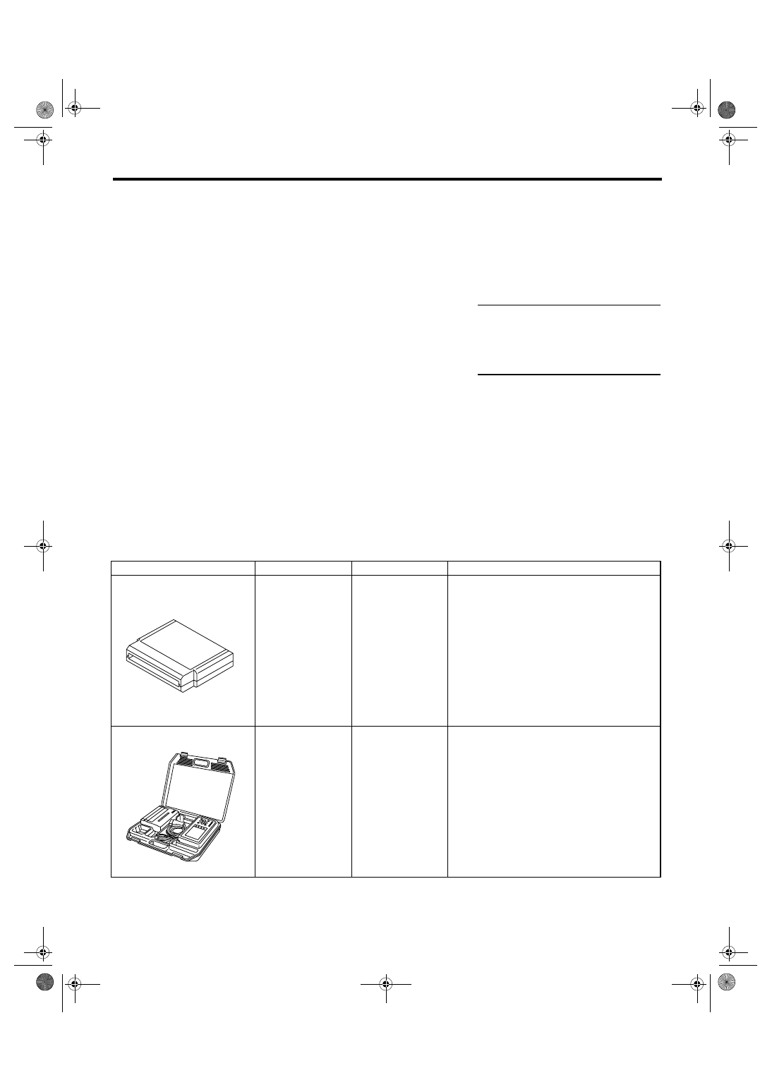
ILLUSTRATION
TOOL NUMBER
DESCRIPTION
REMARKS
18482AA000
(Newly adopted tool)
CARTRIDGE
Troubleshooting for electrical system.
22771AA030
SUBARU SELECT
MONITOR KIT
Troubleshooting for electrical system.
• English: 22771AA030 (Without printer)
• German: 22771AA070 (Without printer)
• French: 22771AA080 (Without printer)
• Spanish: 22771AA090 (Without printer)
ST18482AA000
ST22771AA030
FU(H4SO 2.0)-10
FUEL INJECTION (FUEL SYSTEM)
Throttle Body
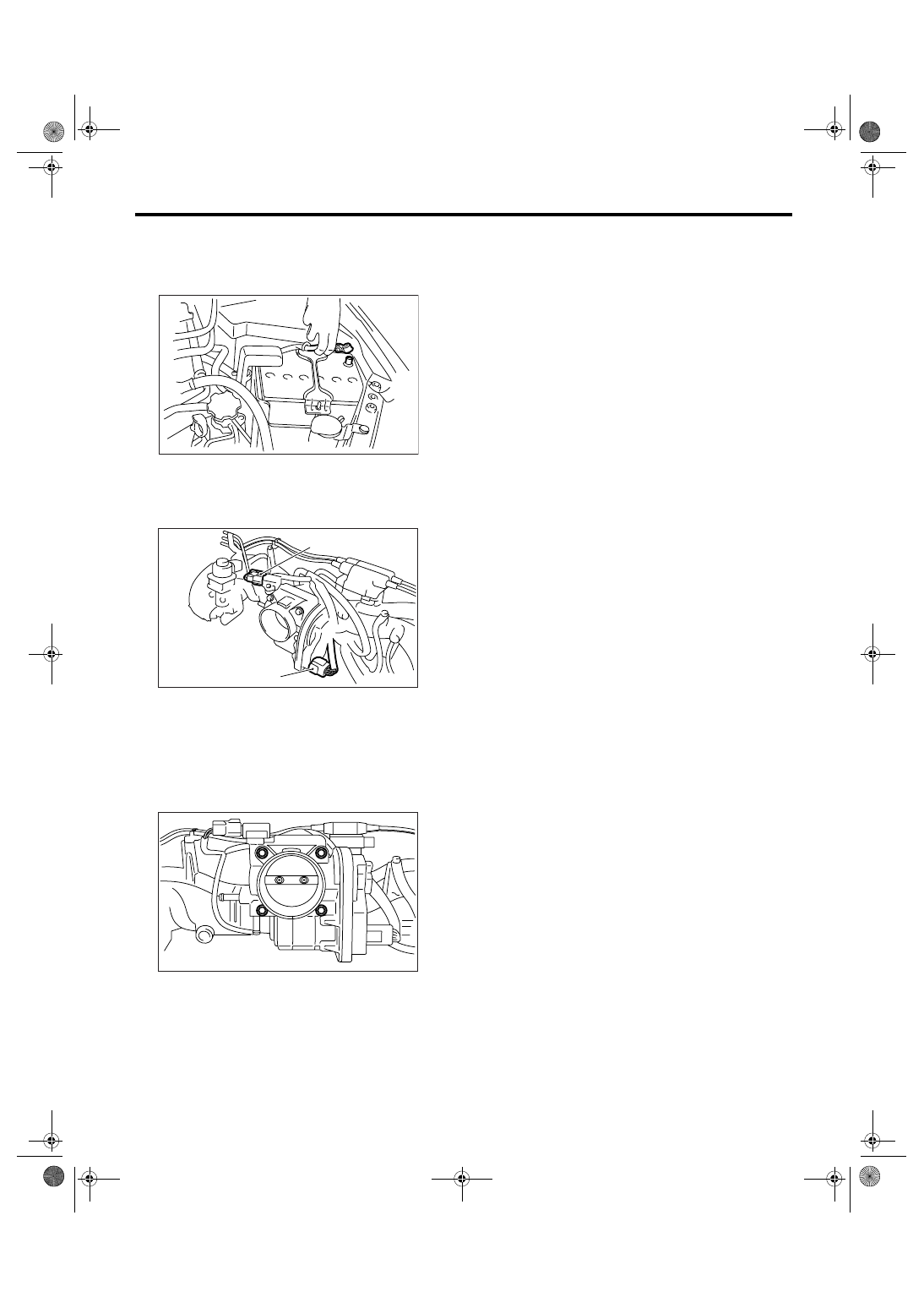
2. Throttle Body
A: REMOVAL
1) Disconnect the ground cable from battery.
2) Remove the air intake chamber. <Ref. to
IN(H4SO 2.0)-7, REMOVAL, Air Intake Chamber.>
3) Disconnect the connectors from the throttle posi-
tion sensor and manifold absolute pressure sensor.
4) Disconnect the engine coolant hoses from throt-
tle body.
5) Remove the bolts which install throttle body to
the intake manifold.
B: INSTALLATION
Install in the reverse order of removal.
NOTE:
Use a new gasket.
Tightening torque:
8 N
⋅
m (0.8 kgf-m, 5.9 ft-lb)
(A) Throttle position sensor
(B) Manifold absolute pressure sensor
IN-00203
FU-02058
(A)
(B)
FU-02059
Нет комментариевНе стесняйтесь поделиться с нами вашим ценным мнением.
Текст