Subaru Legacy (2005 year). Service manual — part 444

EN(H6DO)(diag)-89
ENGINE (DIAGNOSTICS)
Diagnostic Procedure with Diagnostic Trouble Code (DTC)
Step
Check
Yes
No
1
CHECK INPUT SIGNAL OF ECM.
Measure the voltage between ECM connector
and chassis ground.
Connector & terminal
(B135) No. 2 (+) — Chassis ground (
−
):
Is the voltage more than 8 V?
2
CHECK CURRENT DATA.
1) Turn the ignition switch to OFF.
2) Repair the battery short circuit of harness
between ECM and rear oxygen sensor con-
nector.
3) Turn the ignition switch to ON.
4) Read the data of rear oxygen sensor heater
current using Subaru Select Monitor or general
scan tool.
NOTE:
• Subaru Select Monitor
For detailed operation procedure, refer to
“READ CURRENT DATA FOR ENGINE”. <Ref.
to EN(H6DO)(diag)-26, Subaru Select Moni-
tor.>
• General scan tool
For detailed operation procedure, refer to the
general scan tool operation manual.
Is the current more than 7 A?
Replace the ECM.
<Ref. to
FU(H6DO)-34,
Engine Control
Module (ECM).>
Finish the diagno-
sis.
3
CHECK POOR CONTACT.
Check poor contact in ECM connector.
Is there poor contact in ECM
connector?
Repair the poor
contact in ECM
connector.
Finish the diagno-
sis.
EN(H6DO)(diag)-90
ENGINE (DIAGNOSTICS)
Diagnostic Procedure with Diagnostic Trouble Code (DTC)
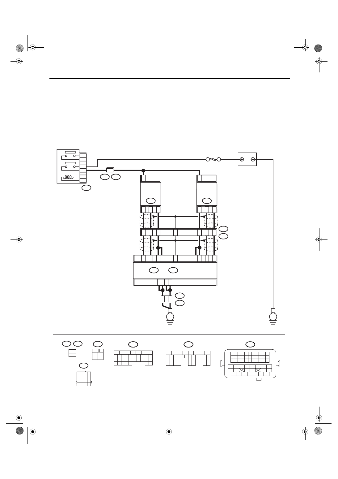
J: DTC P0050 HO2S HEATER CONTROL CIRCUIT (BANK 2 SENSOR 1)
DTC DETECTING CONDITION:
Detects when malfunction occurs in 2 continuous driving cycles.
CAUTION:
After repair or replacement of faulty parts, conduct Clear Memory Mode <Ref. to EN(H6DO)(diag)-41,
OPERATION, Clear Memory Mode.> and Inspection Mode <Ref. to EN(H6DO)(diag)-34, PROCEDURE,
Inspection Mode.>.
WIRING DIAGRAM:
BATTERY
SBF-5
B47
MAIN RELAY
A4
A5
A6
A7
2
52
54
B21
E2
ECM
A34
A27
B7
A1
A2
A3
A26
A33
4
1
3
FRONT
OXYGEN
(A/F)
SENSOR LH
E24
2
B135
B:
B134
A:
4
3
1
FRONT
OXYGEN
(A/F)
SENSOR RH
E47
E3
B22
8
5
6
E3
B22
2
1
3
4
B47
3
4
5
6
1
2
A25
B22
1 2 3 4
5 6 7 8
9 10 11 12
13 14 15 16
3 4
1 2
E47
E24
B135
5
6
7
8
2
1
9
4
3
10
24
22 23
25
11 12 13 14 15
26 27
28
16 17 18 19
20 21
29 30 31
32 33
34 35
B:
B134
5
6
7
8
2
1
9
4
3
10
24
22 23
25
11 12 13 14 15
26 27
28
16 17
18 19 20 21
33 34
29
32
30 31
A:
B21
1 2 3 4
12 13 14 15
5 6 7 8
16 17 18 19
9 10 11
20 21 22
23 24 25 26 27 28 29 30 31 32 33
35
34
37
36
39
38
41
40
43
42
44
45
47
46
49
48
51
50
53
52
54
E
E
EN-03494
B135
B:
B134
A:
7
5
3

EN(H6DO)(diag)-91
ENGINE (DIAGNOSTICS)
Diagnostic Procedure with Diagnostic Trouble Code (DTC)
Step
Check
Yes
No
1
CHECK HARNESS BETWEEN ECM AND
FRONT OXYGEN (A/F) SENSOR CONNEC-
TOR.
1) Start and warm-up the engine.
2) Turn the ignition switch to OFF.
3) Disconnect the connectors from ECM and
front oxygen (A/F) sensor.
4) Measure the resistance of harness
between ECM and front oxygen (A/F) sensor
connector.
Connector & terminal
(B134) No. 1 — (E24) No. 1:
(B135) No. 7 — (E24) No. 1:
Is the resistance less than 1
Ω?
Repair the open
circuit of harness
between ECM and
front oxygen (A/F)
sensor connector.
2
CHECK HARNESS BETWEEN ECM AND
FRONT OXYGEN (A/F) SENSOR CONNEC-
TOR.
Measure the resistance of harness between
ECM and front oxygen (A/F) sensor connector.
Connector & terminal
(B134) No. 27 — (E24) No. 4:
(B134) No. 34 — (E24) No. 3:
Is the resistance less than 1
Ω?
Repair the open
circuit of harness
between ECM and
front oxygen (A/F)
sensor connector.
3
CHECK HARNESS BETWEEN MAIN RELAY
AND FRONT OXYGEN (A/F) SENSOR CON-
NECTOR.
Measure the resistance of harness between
main relay and front oxygen (A/F) sensor con-
nector.
Connector & terminal
(B47) No. 3 — (E24) No. 2:
Is the resistance less than 1
Ω?
Repair the open
circuit of harness
between main
relay and front
oxygen (A/F) sen-
sor connector.
4
CHECK FRONT OXYGEN (A/F) SENSOR.
Measure the resistance between front oxygen
(A/F) sensor connector terminals.
Terminal
No. 2 — No. 1:
Is the resistance less than 5
Ω?
Replace the front
oxygen (A/F) sen-
sor. <Ref. to
FU(H6DO)-30,
Front Oxygen (A/
F) Sensor.>
5
CHECK POOR CONTACT.
Check poor contact in ECM and front oxygen
(A/F) sensor connector.
Is there poor contact in ECM or
front oxygen (A/F) sensor con-
nector?
Repair the poor
contact in ECM or
front oxygen (A/F)
sensor connector.
Replace the front
oxygen (A/F) sen-
sor. <Ref. to
FU(H6DO)-30,
Front Oxygen (A/
F) Sensor.>

EN(H6DO)(diag)-92
ENGINE (DIAGNOSTICS)
Diagnostic Procedure with Diagnostic Trouble Code (DTC)
K: DTC P0051 HO2S HEATER CONTROL CIRCUIT LOW (BANK 2 SENSOR 1)
DTC DETECTING CONDITION:
Immediately at fault recognition
CAUTION:
After repair or replacement of faulty parts, conduct Clear Memory Mode <Ref. to EN(H6DO)(diag)-41,
OPERATION, Clear Memory Mode.> and Inspection Mode <Ref. to EN(H6DO)(diag)-34, PROCEDURE,
Inspection Mode.>.
WIRING DIAGRAM:
BATTERY
SBF-5
B47
MAIN RELAY
A4
A5
A6
A7
2
52
54
B21
E2
ECM
A34
A27
B7
A1
A2
A3
A26
A33
4
1
3
FRONT
OXYGEN
(A/F)
SENSOR LH
E24
2
B135
B:
B134
A:
4
3
1
FRONT
OXYGEN
(A/F)
SENSOR RH
E47
E3
B22
8
5
6
E3
B22
2
1
3
4
B47
3
4
5
6
1
2
A25
B22
1 2 3 4
5 6 7 8
9 10 11 12
13 14 15 16
3 4
1 2
E47
E24
B135
5
6
7
8
2
1
9
4
3
10
24
22 23
25
11 12 13 14 15
26 27
28
16 17 18 19
20 21
29 30 31
32 33
34 35
B:
B134
5
6
7
8
2
1
9
4
3
10
24
22 23
25
11 12 13 14 15
26 27
28
16 17
18 19 20 21
33 34
29
32
30 31
A:
B21
1 2 3 4
12 13 14 15
5 6 7 8
16 17 18 19
9 10 11
20 21 22
23 24 25 26 27 28 29 30 31 32 33
35
34
37
36
39
38
41
40
43
42
44
45
47
46
49
48
51
50
53
52
54
E
E
EN-03494
B135
B:
B134
A:
7
5
3
Нет комментариевНе стесняйтесь поделиться с нами вашим ценным мнением.
Текст