Subaru Legacy (2005 year). Service manual — part 445

EN(H6DO)(diag)-93
ENGINE (DIAGNOSTICS)
Diagnostic Procedure with Diagnostic Trouble Code (DTC)
Step
Check
Yes
No
1
CHECK POWER SUPPLY TO FRONT OXY-
GEN (A/F) SENSOR.
1) Turn the ignition switch to OFF.
2) Disconnect the connector from front oxygen
(A/F) sensor.
3) Turn the ignition switch to ON.
4) Measure the voltage between front oxygen
(A/F) sensor connector and engine ground.
Connector & terminal
(E24) No. 2 (+) — Engine ground (
−
):
Is the voltage more than 10 V? Go to step 2.
Repair the power
supply line.
NOTE:
In this case, repair
the following:
• Open circuit of
harness between
main relay and
front oxygen (A/F)
sensor connector
• Poor contact in
front oxygen (A/F)
sensor connector
• Poor contact in
main relay connec-
tor
2
CHECK GROUND CIRCUIT FOR ECM.
Measure the resistance of harness between
ECM connector and chassis ground.
Connector & terminal
(B134) No. 4 — Chassis ground:
(B134) No. 5 — Chassis ground:
(B134) No. 6 — Chassis ground:
(B134) No. 7 — Chassis ground:
Is the resistance less than 5
Ω?
Repair the har-
ness and connec-
tor.
NOTE:
In this case, repair
the following:
• Open circuit of
harness between
ECM and engine
ground terminal
• Poor contact in
ECM connector
• Poor contact in
coupling connector
3
CHECK CURRENT DATA.
1) Start the engine.
2) Read the data of front oxygen (A/F) sensor
heater current using Subaru Select Monitor or
general scan tool.
NOTE:
• Subaru Select Monitor
For detailed operation procedure, refer to
“READ CURRENT DATA FOR ENGINE”. <Ref.
to EN(H6DO)(diag)-26, Subaru Select Moni-
tor.>
• General scan tool
For detailed operation procedure, refer to the
general scan tool operation manual.
Is the current more than 0.2 A? Repair the poor
contact in connec-
tor.
NOTE:
In this case, repair
the following:
• Poor contact in
front oxygen (A/F)
sensor connector
• Poor contact in
coupling connector
• Poor contact in
ECM connector
4
CHECK OUTPUT SIGNAL FROM ECM.
1) Start and idle the engine.
2) Measure the voltage between ECM con-
nector and chassis ground.
Connector & terminal
(B134) No. 1 (+) — Chassis ground (
−
):
(B135) No. 7 (+) — Chassis ground (
−
):
Is the voltage less than 1 V?
5
CHECK OUTPUT SIGNAL FROM ECM.
Measure the voltage between ECM connector
and chassis ground.
Connector & terminal
(B134) No. 1 (+) — Chassis ground (
−
):
(B135) No. 7 (+) — Chassis ground (
−
):
Does the voltage change by
shaking the ECM harness and
connector while monitoring the
value of voltage meter?
Repair the poor
contact in ECM
connector.

EN(H6DO)(diag)-94
ENGINE (DIAGNOSTICS)
Diagnostic Procedure with Diagnostic Trouble Code (DTC)
6
CHECK FRONT OXYGEN (A/F) SENSOR.
1) Turn the ignition switch to OFF.
2) Measure the resistance between front oxy-
gen (A/F) sensor connector terminals.
Terminal
No. 2 — No. 1:
Is the resistance less than 10
Ω?
Repair the har-
ness and connec-
tor.
NOTE:
In this case, repair
the following:
• Open or ground
short circuit of har-
ness between front
oxygen (A/F) sen-
sor and ECM con-
nector
• Poor contact in
front oxygen (A/F)
sensor connector
• Poor contact in
ECM connector
• Poor contact in
coupling connector
Replace the front
oxygen (A/F) sen-
sor. <Ref. to
FU(H6DO)-30,
Front Oxygen (A/
F) Sensor.>
Step
Check
Yes
No
EN(H6DO)(diag)-95
ENGINE (DIAGNOSTICS)
Diagnostic Procedure with Diagnostic Trouble Code (DTC)
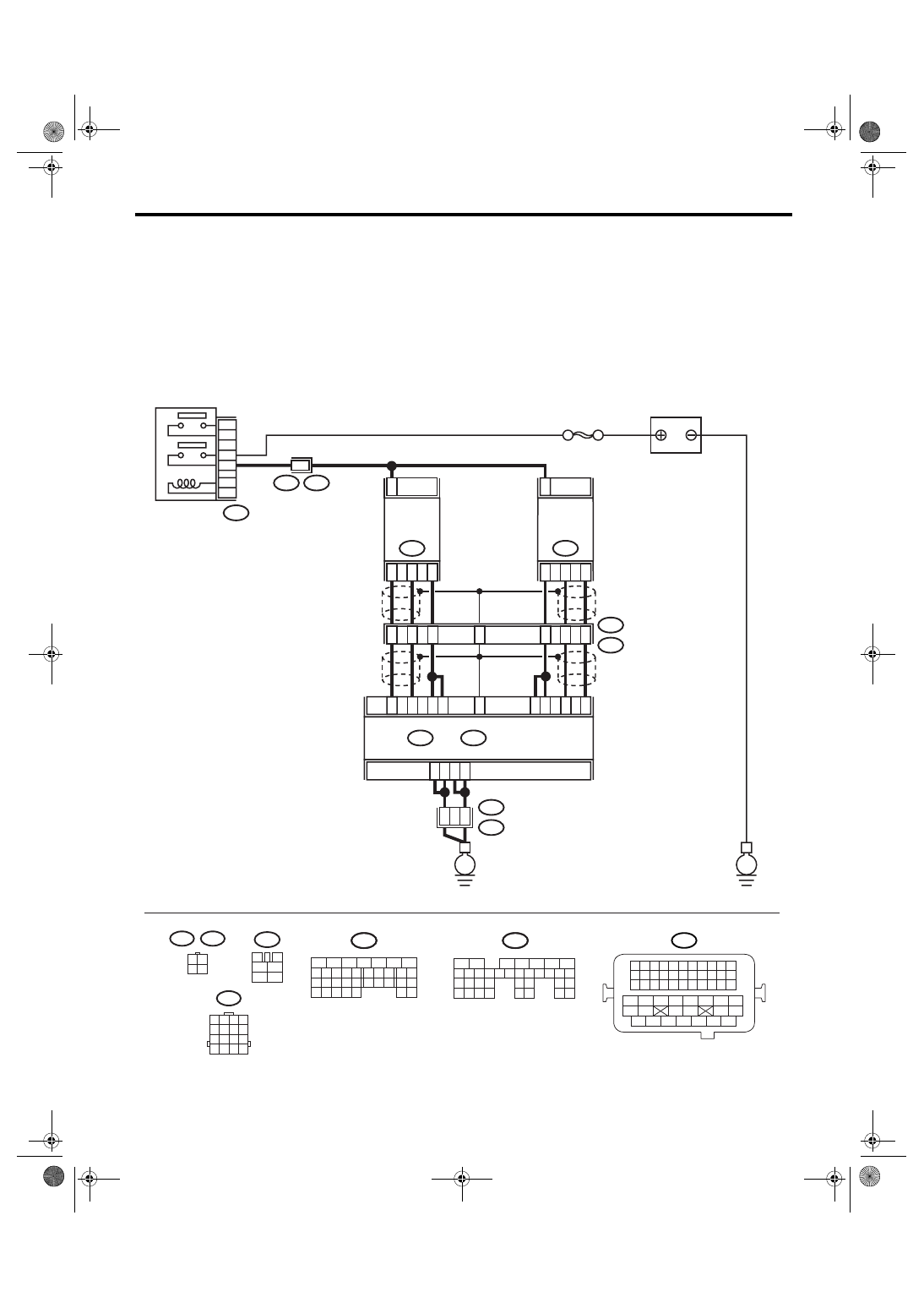
L: DTC P0052 HO2S HEATER CONTROL CIRCUIT HIGH (BANK 2 SENSOR 1)
DTC DETECTING CONDITION:
Immediately at fault recognition
CAUTION:
After repair or replacement of faulty parts, conduct Clear Memory Mode <Ref. to EN(H6DO)(diag)-41,
OPERATION, Clear Memory Mode.> and Inspection Mode <Ref. to EN(H6DO)(diag)-34, PROCEDURE,
Inspection Mode.>.
WIRING DIAGRAM:
BATTERY
SBF-5
B47
MAIN RELAY
A4
A5
A6
A7
2
52
54
B21
E2
ECM
A34
A27
B7
A1
A2
A3
A26
A33
4
1
3
FRONT
OXYGEN
(A/F)
SENSOR LH
E24
2
B135
B:
B134
A:
4
3
1
FRONT
OXYGEN
(A/F)
SENSOR RH
E47
E3
B22
8
5
6
E3
B22
2
1
3
4
B47
3
4
5
6
1
2
A25
B22
1 2 3 4
5 6 7 8
9 10 11 12
13 14 15 16
3 4
1 2
E47
E24
B135
5
6
7
8
2
1
9
4
3
10
24
22 23
25
11 12 13 14 15
26 27
28
16 17 18 19
20 21
29 30 31
32 33
34 35
B:
B134
5
6
7
8
2
1
9
4
3
10
24
22 23
25
11 12 13 14 15
26 27
28
16 17
18 19 20 21
33 34
29
32
30 31
A:
B21
1 2 3 4
12 13 14 15
5 6 7 8
16 17 18 19
9 10 11
20 21 22
23 24 25 26 27 28 29 30 31 32 33
35
34
37
36
39
38
41
40
43
42
44
45
47
46
49
48
51
50
53
52
54
E
E
EN-03494
B135
B:
B134
A:
7
5
3

EN(H6DO)(diag)-96
ENGINE (DIAGNOSTICS)
Diagnostic Procedure with Diagnostic Trouble Code (DTC)
Step
Check
Yes
No
1
CHECK OUTPUT SIGNAL FROM ECM.
1) Turn the ignition switch to ON.
2) Measure the voltage between ECM con-
nector and chassis ground.
Connector & terminal
(B134) No. 1 (+) — Chassis ground (
−
):
(B135) No. 7 (+) — Chassis ground (
−
):
Is the voltage more than 8 V?
2
CHECK FRONT OXYGEN (A/F) SENSOR
HEATER CURRENT.
1) Turn the ignition switch to OFF.
2) Repair the battery short circuit of harness
between ECM and front oxygen (A/F) sensor
connector.
3) Turn the ignition switch to ON.
4) Read the data of front oxygen (A/F) sensor
heater current using Subaru Select Monitor or
general scan tool.
NOTE:
• Subaru Select Monitor
For detailed operation procedure, refer to
“READ CURRENT DATA FOR ENGINE”. <Ref.
to EN(H6DO)(diag)-26, Subaru Select Moni-
tor.>
• General scan tool
For detailed operation procedure, refer to the
general scan tool operation manual.
Is the current more than 2.3 A? Replace the ECM.
<Ref. to
FU(H6DO)-34,
Engine Control
Module (ECM).>
Finish the diagno-
sis.
3
CHECK OUTPUT SIGNAL FROM ECM.
Measure the voltage between ECM connector
and chassis ground.
Connector & terminal
(B134) No. 1 (+) — Chassis ground (
−
):
(B135) No. 7 (+) — Chassis ground (
−
):
Does the voltage change by
shaking the ECM harness and
connector?
Repair the battery
short circuit of har-
ness between
ECM and front
oxygen (A/F) sen-
sor connector.
Finish the diagno-
sis.
Нет комментариевНе стесняйтесь поделиться с нами вашим ценным мнением.
Текст