Subaru Legacy (2005 year). Service manual — part 242

EN(H4SO 2.5)(diag)-253
ENGINE (DIAGNOSTICS)
Diagnostic Procedure with Diagnostic Trouble Code (DTC)
7
CHECK ACCELERATOR PEDAL POSITION
SENSOR.
Measure the resistance of accelerator pedal
position sensor.
Terminals
No. 3 — No. 4:
Is the resistance 1.2 — 4.8
k
Ω?
Replace the accel-
erator pedal posi-
tion sensor.
8
CHECK ACCELERATOR PEDAL POSITION
SENSOR.
Measure the resistance of accelerator pedal
position sensor.
Terminals
No. 1 — No. 6:
Is the resistance 0.75 — 3.15
k
Ω?
Replace the accel-
erator pedal posi-
tion sensor.
9
CHECK ACCELERATOR PEDAL POSITION
SENSOR.
Measure the resistance of accelerator pedal
position sensor without depressing the accel-
erator pedal.
Terminals
No. 5 — No. 4:
Is the resistance 0.2 — 0.8
k
Ω?
Replace the accel-
erator pedal posi-
tion sensor.
10
CHECK ACCELERATOR PEDAL POSITION
SENSOR.
Measure the resistance of accelerator pedal
position sensor without depressing the accel-
erator pedal.
Terminals
No. 2 — No. 6:
Is the resistance 0.15 — 0.63
k
Ω?
Replace the accel-
erator pedal posi-
tion sensor.
11
CHECK ACCELERATOR PEDAL POSITION
SENSOR.
Measure the resistance of accelerator pedal
position sensor with depressing the accelera-
tor pedal.
Terminals
No. 5 — No. 4:
Is the resistance 0.5 — 2.5
k
Ω?
Replace the accel-
erator pedal posi-
tion sensor.
12
CHECK ACCELERATOR PEDAL POSITION
SENSOR.
Measure the resistance of accelerator pedal
position sensor with depressing the accelera-
tor pedal.
Terminals
No. 2 — No. 6:
Is the resistance 0.28 — 1.68
k
Ω?
Replace the accel-
erator pedal posi-
tion sensor.
13
CHECK ACCELERATOR PEDAL POSITION
SENSOR OUTPUT.
1) Turn the ignition switch to OFF.
2) Connect all the connectors.
3) Turn the ignition switch to ON.
4) Read the data of main throttle sensor signal
and sub accelerator pedal position sensor sig-
nal using Subaru Select Monitor.
NOTE:
For detailed operation procedure, refer to
“READ CURRENT DATA FOR ENGINE”. <Ref.
to EN(H4SO 2.5)(diag)-25, Subaru Select Mon-
itor.>
Is the voltage less than 4.8 V? Go to step 14.
14
CHECK POOR CONTACT.
Check poor contact in connector between
ECM and accelerator pedal position sensor.
Is there poor contact?
Repair the poor
contact.
Step
Check
Yes
No

EN(H4SO 2.5)(diag)-254
ENGINE (DIAGNOSTICS)
Diagnostic Procedure with Diagnostic Trouble Code (DTC)
CL:DTC P2503 CHARGING SYSTEM VOLTAGE LOW
NOTE:
For the diagnostic procedure, refer to DTC P2504. <Ref. to EN(H4SO 2.5)(diag)-255, DTC P2504 CHARG-
ING SYSTEM VOLTAGE HIGH, Diagnostic Procedure with Diagnostic Trouble Code (DTC).>
15
CHECK HARNESS BETWEEN ECM AND AC-
CELERATOR PEDAL POSITION SENSOR.
1) Turn the ignition switch to OFF.
2) Disconnect the connector from ECM.
3) Disconnect the connectors from accelerator
pedal position sensor.
4) Measure the resistance between ECM con-
nector and accelerator pedal position sensor
connector.
Connector & terminal
(B136) No. 34 — (B315) No. 4:
(B136) No. 35 — (B315) No. 6:
Is the resistance less than 1
Ω?
Repair the open
circuit of harness
connector.
16
CHECK HARNESS BETWEEN ECM AND AC-
CELERATOR PEDAL POSITION SENSOR.
1) Connect the ECM connector.
2) Measure the resistance between accelera-
tor pedal position sensor connector and engine
ground.
Connector & terminal
(B315) No. 4 — Engine ground:
(B315) No. 6 — Engine ground:
Is the resistance less than 5
Ω?
Repair the poor
contact in ECM
connector.
Replace the ECM
if defective. <Ref.
to FU(H4SO 2.5)-
37, Engine Con-
trol Module
(ECM).>
17
CHECK HARNESS BETWEEN ECM AND AC-
CELERATOR PEDAL POSITION SENSOR.
1) Connect the ECM connector.
2) Turn the ignition switch to ON.
3) Measure the voltage between accelerator
pedal position sensor connector and engine
ground.
Connector & terminal
(B315) No. 5 (+) — Engine ground (
−
):
(B315) No. 2 (+) — Engine ground (
−
):
Is the voltage less than 6 V?
Repair the battery
short circuit of har-
ness between
ECM connector
and accelerator
pedal position sen-
sor connector.
18
CHECK HARNESS BETWEEN ECM AND AC-
CELERATOR PEDAL POSITION SENSOR.
1) Turn the ignition switch to OFF.
2) Disconnect the connector from ECM.
3) Measure the resistance between ECM con-
nectors.
Connector & terminal
(B136) No. 17 — (B136) No. 15:
(B136) No. 17 — (B136) No. 16:
(B136) No. 28 — (B136) No. 15:
(B136) No. 28 — (B136) No. 16:
Is the resistance more than 1
M
Ω?
Repair the short
circuit to sensor
power supply.
19
CHECK HARNESS BETWEEN ECM AND AC-
CELERATOR PEDAL POSITION SENSOR.
1) Turn the ignition switch to OFF.
2) Disconnect the connector from ECM.
3) Disconnect the connectors from accelerator
pedal position sensor.
4) Measure the resistance between connector
terminals of accelerator pedal position sensor.
Connector & terminal
(B315) No. 5 — (B315) No. 2:
Is the resistance more than 1
M
Ω?
Repair the poor
contact in ECM
connector.
Replace the ECM
if defective. <Ref.
to FU(H4SO 2.5)-
37, Engine Con-
trol Module
(ECM).>
Repair the short
circuit of harness
between ECM
connector and
accelerator pedal
position sensor
connector.
Step
Check
Yes
No
EN(H4SO 2.5)(diag)-255
ENGINE (DIAGNOSTICS)
Diagnostic Procedure with Diagnostic Trouble Code (DTC)
CM:DTC P2504 CHARGING SYSTEM VOLTAGE HIGH
DTC DETECTING CONDITION:
Immediately at fault recognition
CAUTION:
After repair or replacement of faulty parts, conduct Clear Memory Mode <Ref. to EN(H4SO 2.5)(diag)-
40, Clear Memory Mode.> and Inspection Mode <Ref. to EN(H4SO 2.5)(diag)-33, Inspection Mode.>.
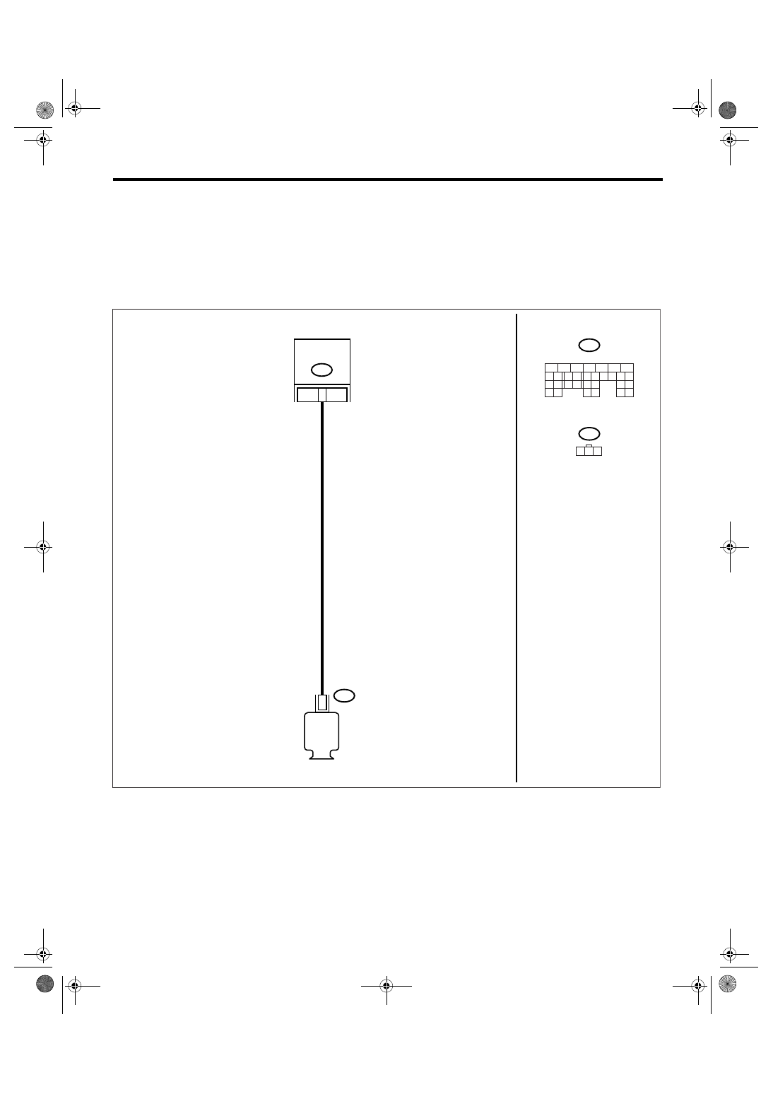
WIRING DIAGRAM:
• EC, EK, EH, ER and K4 model
• KA and KS model
NOTE:
Fuel injection system for KA and KS model is the same as 2.0 L model. Refer to EN(H4SO 2.0) section.
EN-02465
B134
F26
B134
F26
ECM
GENERATOR
22
3
1 2 3
5
6
7
8
2
1
9
4
3
10
22 23
11 12 13 14 15
24 25
26
16 17
18 19 20 21
27
28 29
30 31

EN(H4SO 2.5)(diag)-256
ENGINE (DIAGNOSTICS)
Diagnostic Procedure with Diagnostic Trouble Code (DTC)
Step
Check
Yes
No
1
CHECK OPTION CODE.
Is the option code EC, EK, EH,
ER or K4?
Refer to EN(H4SO
2.0) section. <Ref.
to EN(H4SO
2.0)(diag)-64, List
of Diagnostic Trou-
ble Code (DTC).>
NOTE:
Fuel injection sys-
tem for KA and KS
model is the same
as 2.0 L model.
2
CHECK HARNESS BETWEEN GENERATOR
AND ECM CONNECTOR.
1) Turn the ignition switch to OFF.
2) Disconnect the connectors from generator
and ECM.
3) Measure the resistance of harness
between generator connector and engine
ground.
Connector & terminal
(F26) No. 3 — Engine ground:
Is the resistance more than 1
M
Ω?
Repair the ground
short circuit of har-
ness between
ECM and purge
control solenoid
valve connector.
3
CHECK HARNESS BETWEEN GENERATOR
AND ECM CONNECTOR.
Measure the resistance of harness between
ECM and generator.
Connector & terminal
(B134) No. 22 — (F26) No. 3:
Is the resistance less than 1
Ω?
Repair the poor
contact in connec-
tor.
Repair the open
circuit of harness
between ECM and
generator connec-
tor.
NOTE:
In this case, repair
the following:
• Open circuit of
harness between
ECM and genera-
tor connector
• Poor contact in
coupling connector
Нет комментариевНе стесняйтесь поделиться с нами вашим ценным мнением.
Текст