Subaru Legacy (2005 year). Service manual — part 1017
CC(diag)-5
CRUISE CONTROL SYSTEM (DIAGNOSTICS)
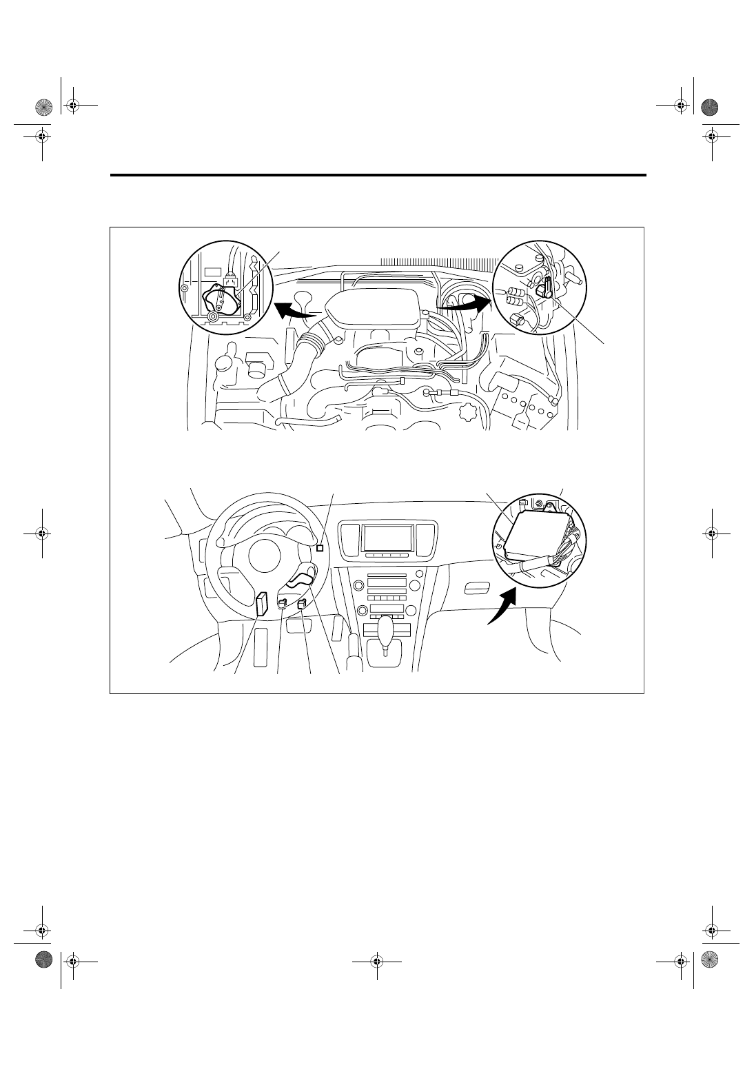
Electrical Component Location
3. Electrical Component Location
A: LOCATION
(1)
Engine control module (ECM)
(5)
Transmission control module
(TCM) (AT model)
(7)
Neutral position switch (MT
model)
(2)
Cruise control command switch
(3)
Stop and brake switch
(6)
Inhibitor switch (AT model)
(8)
Clutch switch (MT model)
(4)
Cruise indicator light and cruise
set indicator light
CC-00263
(7)
(6)
(1)
(4)
(2)
(3)
(8)
(5)
CC(diag)-6
CRUISE CONTROL SYSTEM (DIAGNOSTICS)
Engine Control Module (ECM) I/O Signal
4. Engine Control Module (ECM) I/O Signal
A: ELECTRICAL SPECIFICATION
• 2.0 L turbo model, 3.0 L model, 2.5 L EC, K4 and EK model
Content
Termi-
nal No.
Measurement Condition and I/O Signal
(Idling with ignition ON: Except cruise set light)
Main power
supply
VB (CONTROL 1)
VB (CONTROL 2)
B6
B5
• Battery voltage is present when the main power is turned ON.
• “0 V” voltage is present when the main power is turned OFF.
Command Switch
C11
• “0 V” voltage is present when the command switch is turned to CANCEL posi-
tion.
• “Approx. 1 V” voltage is present when the command switch is turned to SET/
COAST position.
• “Approx. 3 V” voltage is present when the command switch is turned to
RESUME/ACCEL position.
• “Approx. 4 V” voltage is present when the command switch is released.
Brake switch 1
(Brake switch)
C9
• Battery voltage is present when the brake pedal is released.
• “0 V” voltage is present when the brake pedal is depressed.
Brake switch 2
(Stop light switch)
C8
• Battery voltage is present when the brake pedal is depressed.
• “0 V” voltage is present when the brake pedal is released.
Main switch
C7
• “0 V” voltage is present while the main switch is pressed or turned ON.
• Battery voltage is present when the main switch is turned OFF.
Ground
GND (CONTROL 1)
GND (CONTROL 2)
D2
D1
—
Ignition switch
D14
• Battery voltage is present when the ignition switch is turned ON.
• “0 V” voltage is present when the ignition switch is turned OFF.
Clutch switch (MT model)
C10
• “0 V” voltage is present when the clutch pedal is depressed.
• Battery voltage is present when the clutch pedal is released.
Neutral position switch (MT model)
D9
• “0 V” voltage is present when the shift lever is set in any position except neu-
tral.
• “Approx. 5 V” voltage is present when the shift lever is set in neutral position.
Neutral signal (AT model)
D9
• “Approx. 5 V” voltage (4AT model) or battery voltage (5AT model) is present
when the shift lever is set in any position except “P” or “N”.
• “0 V” voltage is present when the shift lever is set in “P” or “N” position.
CC-00197
B134
9
30 29 28
32 31
20 19 18
22 21
10
12 11
14
24
34 33
27 26
17 16
1
2
3
4
5
6
7
13
23
15
25
8
B135
9
30 29 28
32
31
20
22 21
10
12 11
14
24
35
33
27 26
17 16
1
2
3
4
5
6
7
13
23
15
25
8
B136
9
30 29 28
32 31
20 19 18
22 21
10
12 11
14
24
34 33
27 26
16
1
2
3
4
5
6
13
23
15
25
8
B137
9
29 28
20 19 18
22 21
10
12 11
14
24
17 16
1
2
3
4
5
6
7
13
23
15
25
8
18
19
34
7
17
35
30
31
27 26
To D:
To C:
To B:
To A:

CC(diag)-7
CRUISE CONTROL SYSTEM (DIAGNOSTICS)
Engine Control Module (ECM) I/O Signal
• 2.0 L non-turbo model, 2.5 L KS, KA model
B: WIRING DIAGRAM
<Ref. to WI-213, WIRING DIAGRAM, Cruise Control System.>
Content
Termi-
nal No.
Measurement Condition and I/O Signal
(Idling with ignition ON: Except cruise set light)
Main power
supply
VB (CONTROL 1)
VB (CONTROL 2)
C3
C4
• Battery voltage is present when the main power is turned ON.
• “0 V” voltage is present when the main power is turned OFF.
Command Switch
C21
• “0 V” voltage is present when the command switch is turned to CANCEL posi-
tion.
• “Approx. 1 V” voltage is present when the command switch is turned to SET/
COAST position.
• “Approx. 3 V” voltage is present when the command switch is turned to
RESUME/ACCEL position.
• “Approx. 4 V” voltage is present when the command switch is released.
Brake switch 1
(Brake switch)
D12
• Battery voltage is present when the brake pedal is released.
• “0 V” voltage is present when the brake pedal is depressed.
Brake switch 2
(Stop light switch)
D13
• Battery voltage is present when the brake pedal is depressed.
• “0 V” voltage is present when the brake pedal is released.
Main switch
D14
• “0 V” voltage is present while the main switch is pressed or turned ON.
• Battery voltage is present when the main switch is turned OFF.
Ground
GND (CONTROL 1)
GND (CONTROL 2)
C5
C6
—
Ignition switch
B13
• Battery voltage is present when the ignition switch is turned ON.
• “0 V” voltage is present when the ignition switch is turned OFF.
Clutch switch (MT model)
D22
• “0 V” voltage is present when the clutch pedal is depressed.
• Battery voltage is present when the clutch pedal is released.
Neutral position switch (MT model)
B12
• “0 V” voltage is present when the shift lever is set in any position except neu-
tral.
• “Approx. 5 V” voltage is present when the shift lever is set in neutral position.
Neutral signal (AT model)
B12
• “Approx. 5 V” voltage is present when the shift lever is set in any position
except “P” or “N”.
• “0 V” voltage is present when the shift lever is set in “P” or “N” position.
CC(diag)-8
CRUISE CONTROL SYSTEM (DIAGNOSTICS)
Subaru Select Monitor
5. Subaru Select Monitor
A: OPERATION
1. GENERAL DESCRIPTION
For the on-board diagnosis function of the cruise
control system, use Subaru Select Monitor.
The on-board diagnosis function operates under
two categories, which are used depending on the
type of problems;
1) Cruise Control Cancel Conditions Diagnosis
(1) This category of diagnosis requires actual
vehicle driving in order to determine the cause,
as when cruise speed is cancelled during driving
although cruise cancel condition is not entered.
(2) Cruise control memory in ECM stores the
cancel condition (Code No.) which occurred dur-
ing driving. When there are plural cancel condi-
tions (Code No.), they are shown on the Subaru
Select Monitor.
CAUTION:
• The cruise control memory stores not only
the cruise “cancel” which occurred (although
“cancel” operation is not entered by the driver),
but also the “cancel” condition input by the
driver.
• The content of memory is cleared when igni-
tion switch or cruise control main switch is
turned OFF.
2) Real-time Diagnosis
Real-time diagnosis function is used to determine
whether or not the input signal system is in good or-
der, according to the signal emitted from switches,
sensors, etc.
(1) Vehicle cannot be driven at cruise speed
when problem occurs in the cruise control sys-
tem or its associated circuits.
(2) Monitor the signal conditions from switches
and sensors.
2. CRUISE CONTROL CANCEL CONDI-
TIONS DIAGNOSIS
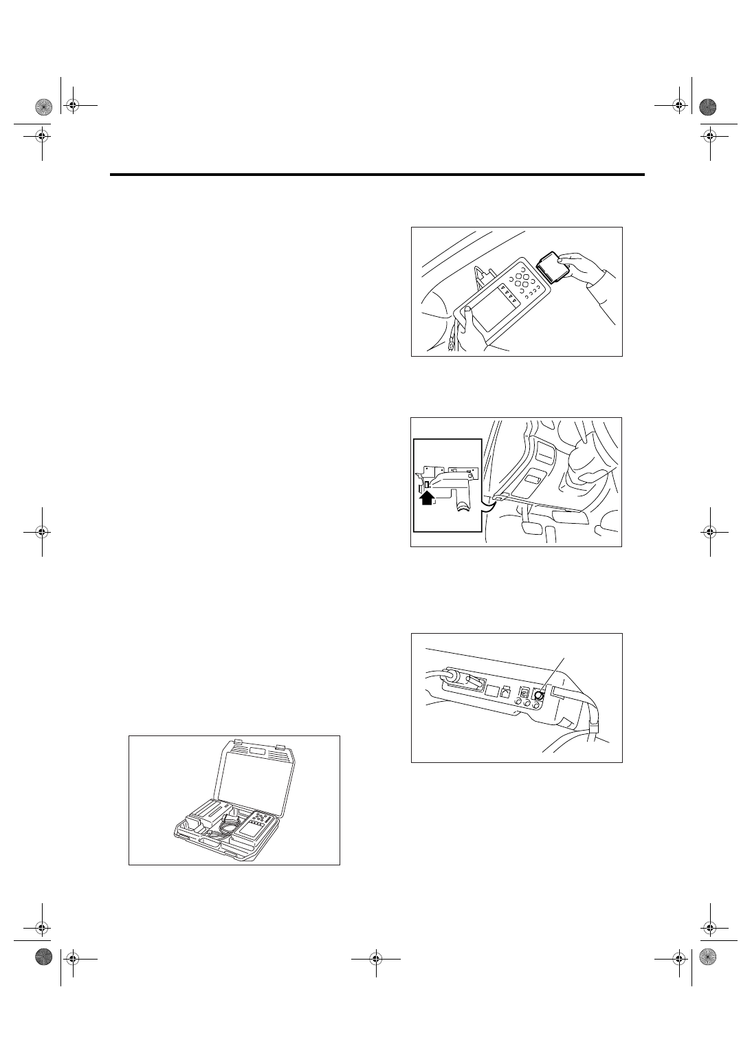
1) Prepare the Subaru Select Monitor kit.
2) Connect the diagnosis cable to Subaru Select
Monitor.
3) Insert the cartridge to Subaru Select Monitor.
<Ref. to CC(diag)-4, SPECIAL TOOL, PREPARA-
TION TOOL, General Description.>
4) Connect the Subaru Select Monitor to data link
connector.
(1) Data link connector is located in the lower
portion of instrument panel (on the driver’s side).
(2) Connect the diagnosis cable to data link
connector.
5) Start the engine and turn the cruise control main
switch to ON.
6) Turn the Subaru Select Monitor power switch to
ON.
7) On the « Main Menu» display screen, select the
{Each System Check} and press the [YES] key.
On the system selection display screen, select the
{Engine} and press the [YES] key. Press the [YES]
key after the information of engine type is dis-
played.
8) Drive vehicle at least 40 km/h (25 MPH) with
cruise speed set.
CC-00028
(1) Power switch
EN-00039
IM-00084
CC-00045
(1)
Нет комментариевНе стесняйтесь поделиться с нами вашим ценным мнением.
Текст