Subaru Legacy (2005 year). Service manual — part 351
EN(H4DOTC)(diag)-173
ENGINE (DIAGNOSTICS)
Diagnostic Procedure with Diagnostic Trouble Code (DTC)
Step
Check
Yes
No
1
CHECK HARNESS BETWEEN ECM AND OIL
FLOW CONTROL SOLENOID VALVE.
1) Turn the ignition switch to OFF.
2) Disconnect the connectors from ECM and
oil flow control solenoid valve.
3) Measure the resistance between ECM and
oil flow control solenoid valve.
Connector & terminal
(B134) No. 20 — (E63) No. 1:
(B134) No. 30 — (E63) No. 2:
Is the resistance less than 1
Ω?
Repair the open
circuit of harness
between ECM and
oil flow control
solenoid valve
connector.
NOTE:
In this case, repair
the following:
• Open circuit of
harness between
ECM and oil flow
control solenoid
valve connector
• Poor contact in
coupling connector
2
CHECK OIL FLOW CONTROL SOLENOID
VALVE.
1) Disconnect the oil flow control solenoid
valve connector.
2) Measure the resistance between oil flow
control solenoid valve terminals.
Terminals
No. 1 — No. 2:
Is the resistance 6 — 12
Ω?
Repair the poor
contact in ECM
and oil flow con-
trol solenoid valve.
Replace the oil
flow control sole-
noid valve. <Ref.
to ME(H4DOTC)-
56, Camshaft.>
EN(H4DOTC)(diag)-174
ENGINE (DIAGNOSTICS)
Diagnostic Procedure with Diagnostic Trouble Code (DTC)
BH:DTC P2091 EXHAUST CAMSHAFT POSITION ACTUATOR CONTROL CIR-
CUIT HIGH (BANK 1)
DTC DETECTING CONDITION:
Immediately at fault recognition
TROUBLE SYMPTOM:
Erroneous idling
CAUTION:
After repair or replacement of faulty parts, perform Clear Memory Mode <Ref. to EN(H4DOTC)(diag)-
37, OPERATION, Clear Memory Mode.> and Inspection Mode <Ref. to EN(H4DOTC)(diag)-30, PROCE-
DURE, Inspection Mode.>.
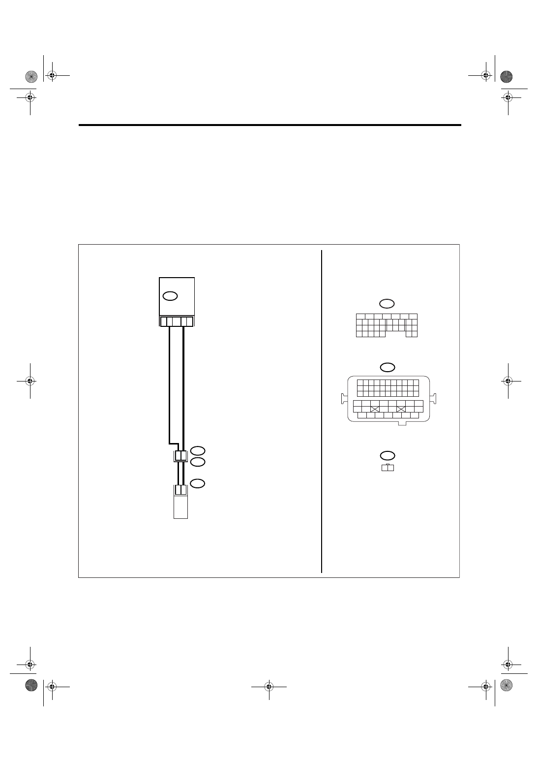
WIRING DIAGRAM:
EN-01961
B21
E2
B134
E63
30
2
1
26
25
E63
B21
1 2
20
B134
5
6
7
8
2
1
9
4
3
10
24
22 23
25
11 12 13 14 15
26 27
28
16 17
18 19 20 21
33 34
29
32
30 31
ECM
1 2 3 4
12 13 14 15
5 6 7 8
16 17 18 19
9 10 11
20 21 22
23 24 25 26 27 28 29 30 31 32 33
35
34
37
36
39
38
41
40
43
42
44
45
47
46
49
48
51
50
53
52
54
OIL FLOW CONTROL
SOLENOID VALVE RH
EN(H4DOTC)(diag)-175
ENGINE (DIAGNOSTICS)
Diagnostic Procedure with Diagnostic Trouble Code (DTC)
Step
Check
Yes
No
1
CHECK HARNESS BETWEEN ECM AND OIL
FLOW CONTROL SOLENOID VALVE.
1) Turn the ignition switch to OFF.
2) Disconnect the connectors from ECM and
oil flow control solenoid valve.
3) Measure the resistance between oil flow
control solenoid valve and engine ground.
Connector & terminal
(E63) No. 1 — Engine ground:
(E63) No. 2 — Engine ground:
Is the resistance more than 1
M
Ω?
Repair the short
circuit between
ECM and oil flow
control solenoid
valve connector.
2
CHECK OIL FLOW CONTROL SOLENOID
VALVE.
1) Disconnect the oil flow control solenoid
valve connector.
2) Measure the resistance between oil flow
control solenoid valve terminals.
Terminals
No. 1 — No. 2:
Is the resistance 6 — 12
Ω?
Repair the poor
contact in ECM
and oil flow con-
trol solenoid valve.
Replace the oil
flow control sole-
noid valve. <Ref.
to ME(H4DOTC)-
56, Camshaft.>
EN(H4DOTC)(diag)-176
ENGINE (DIAGNOSTICS)
Diagnostic Procedure with Diagnostic Trouble Code (DTC)
BI: DTC P2092 INTAKE CAMSHAFT POSITION ACTUATOR CONTROL CIRCUIT
LOW (BANK 2)
DTC DETECTING CONDITION:
Immediately at fault recognition
TROUBLE SYMPTOM:
Erroneous idling
CAUTION:
After repair or replacement of faulty parts, perform Clear Memory Mode <Ref. to EN(H4DOTC)(diag)-
37, OPERATION, Clear Memory Mode.> and Inspection Mode <Ref. to EN(H4DOTC)(diag)-30, PROCE-
DURE, Inspection Mode.>.
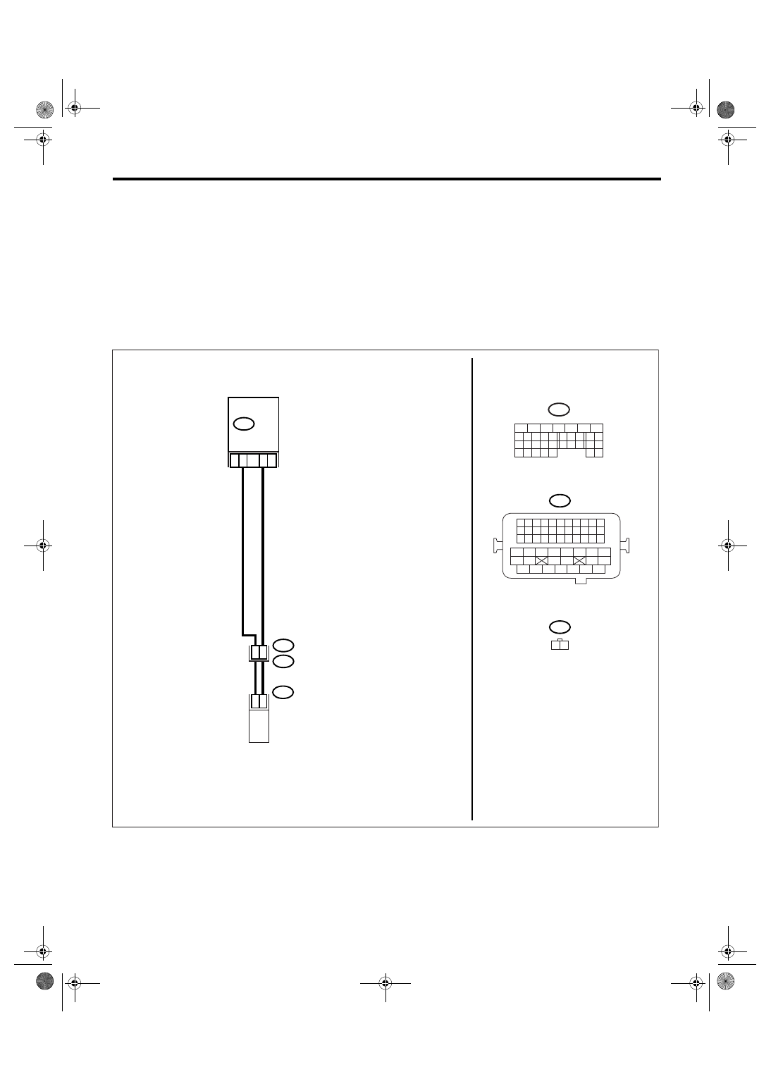
WIRING DIAGRAM:
EN-01962
B21
E2
B134
E37
29
2
1
28
27
E37
B21
1 2
19
B134
5
6
7
8
2
1
9
4
3
10
24
22 23
25
11 12 13 14 15
26 27
28
16 17
18 19 20 21
33 34
29
32
30 31
ECM
1 2 3 4
12 13 14 15
5 6 7 8
16 17 18 19
9 10 11
20 21 22
23 24 25 26 27 28 29 30 31 32 33
35
34
37
36
39
38
41
40
43
42
44
45
47
46
49
48
51
50
53
52
54
OIL FLOW CONTROL
SOLENOID VALVE LH
Нет комментариевНе стесняйтесь поделиться с нами вашим ценным мнением.
Текст