Subaru Legacy (2005 year). Service manual — part 679
6MT-63
MANUAL TRANSMISSION AND DIFFERENTIAL
Oil Pump
5) If replacing the oil pump cover assembly, select
the transfer driven gear and thrust washer, then in-
stall them to the extension case. <Ref. to 6MT-49,
ADJUSTMENT, Extension Case.>
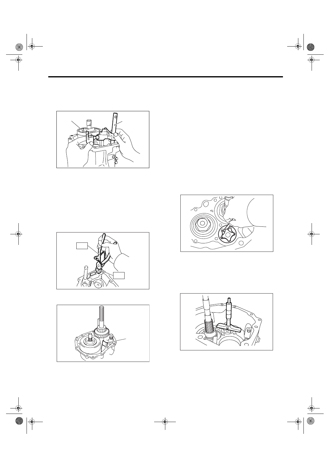
6) Remove the selector arm No. 2 and shifter arm.
7) Install the spring pin.
NOTE:
Use new spring pin.
8) Using the ST, install the neutral set spring and
support.
ST1
18756AA000 CLAW
ST2
399893600
PLIERS
9) Install the flat washer and snap ring.
10) Install the oil guide.
11) Install the center differential. <Ref. to 6MT-60,
INSTALLATION, Center Differential.>
12) Install the transfer driven gear. <Ref. to 6MT-
58, INSTALLATION, Transfer Driven Gear.>
13) Install the extension case. <Ref. to 6MT-47, IN-
STALLATION, Extension Case.>
14) Install the manual transmission assembly into
vehicle. <Ref. to 6MT-36, INSTALLATION, Manual
Transmission Assembly.>
C: INSPECTION
1) Check that there is no damage on the inner rotor
and outer rotor. Replace the oil pump rotor assem-
bly if damaged.
2) Tip clearance
Install the inner rotor and outer rotor to transmis-
sion case. Align tip of the inner rotor and outer ro-
tor, then measure the clearance. Replace the oil
pump rotor assembly if clearance exceeds specifi-
cation.
Tip clearance specification:
Less than 0.15 mm (0.0059 in)
3) Side clearance
Measure to the transmission case and rotor. Re-
place the oil pump rotor assembly if clearance ex-
ceeds specification.
Side clearance specification:
0.03 — 0.10 mm (0.0012 — 0.0039 in)
(A) Selector arm No. 2
(B) Shifter arm
(A) Oil guide
(B)
(A)
MT-01308
MT-01092
ST2
ST2
ST1
MT-00520
(A)
MT-00524
MT-00525
6MT-64
MANUAL TRANSMISSION AND DIFFERENTIAL
Transmission Case
18.Transmission Case
A: REMOVAL
1) Remove the manual transmission assembly
from vehicle. <Ref. to 6MT-34, REMOVAL, Manual
Transmission Assembly.>
2) Prepare the transmission for overhaul. <Ref. to
6MT-40, Preparation for Overhaul.>
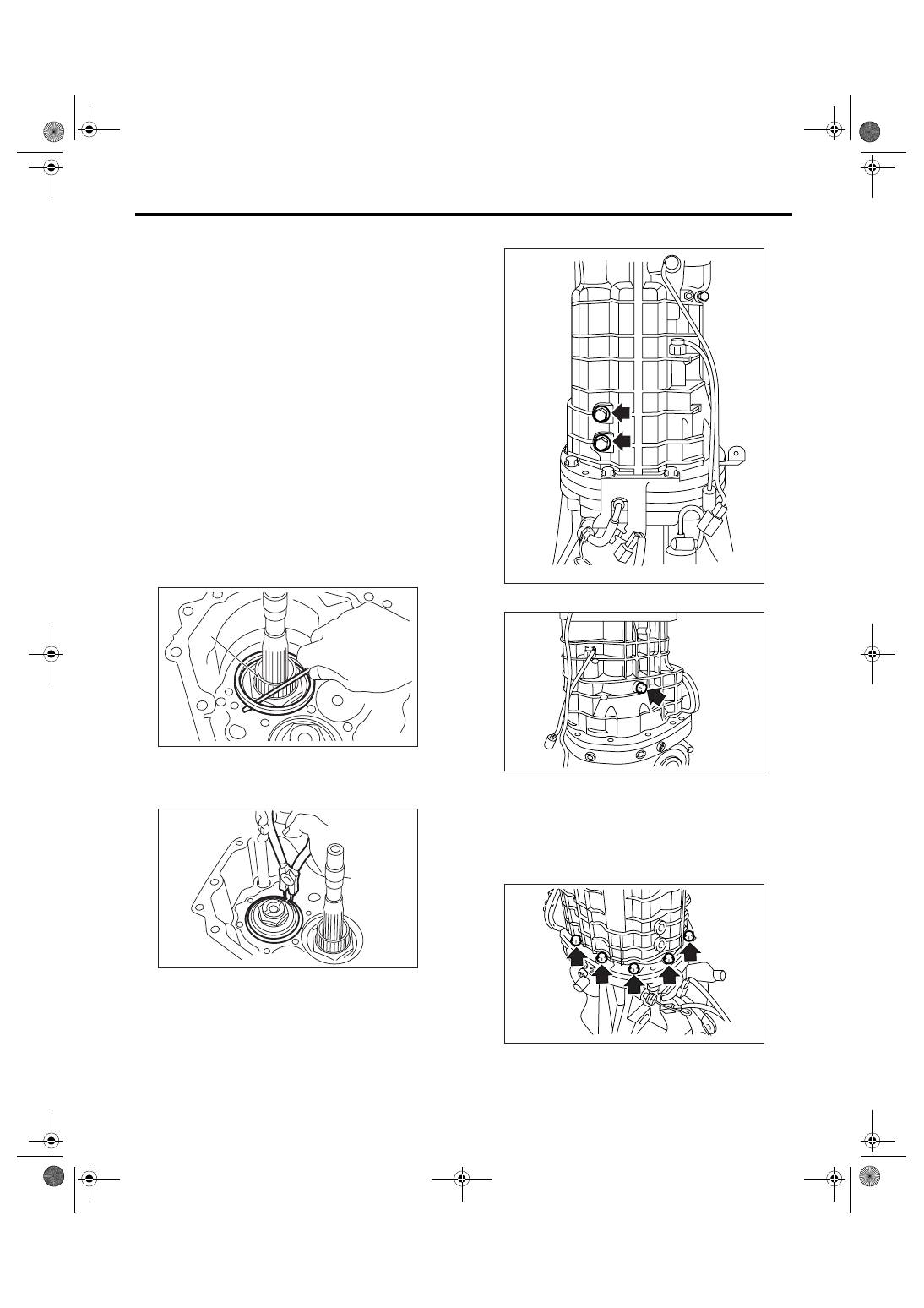
3) Remove the oil pipe, neutral position switch,
back-up light switch and harness. <Ref. to 6MT-42,
REMOVAL, Oil Pipe.> <Ref. to 6MT-45, REMOV-
AL, Neutral Position Switch.> <Ref. to 6MT-43, RE-
MOVAL, Back-up Light Switch.>
4) Remove the extension case. <Ref. to 6MT-47,
REMOVAL, Extension Case.>
5) Remove the transfer driven gear. <Ref. to 6MT-
58, REMOVAL, Transfer Driven Gear.>
6) Remove the center differential. <Ref. to 6MT-60,
REMOVAL, Center Differential.>
7) Remove the oil pump. <Ref. to 6MT-61, RE-
MOVAL, Oil Pump.>
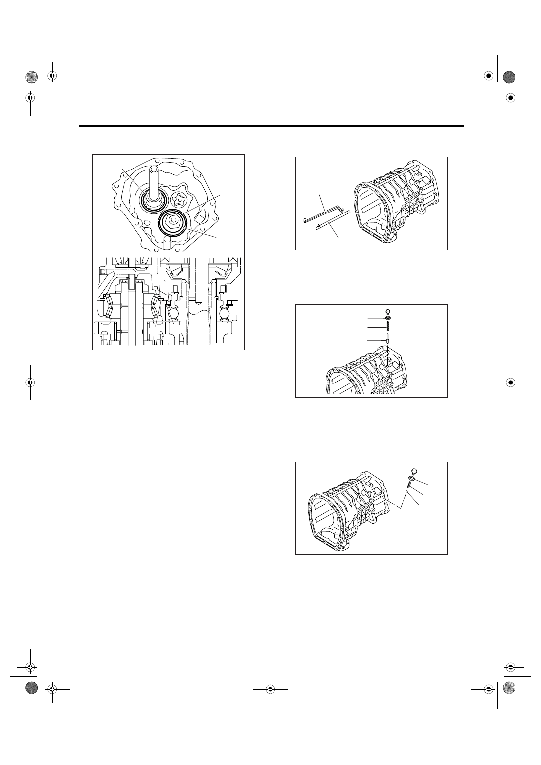
8) Remove the shim and spacer of driven gear as-
sembly.
9) Remove the snap ring.
10) Remove the pilot bolt.
11) Remove the holder reverse bolt.
12) Remove the transmission case.
NOTE:
If the oil guide catches on shift fork, the transmis-
sion case may be difficult to be removed. Move the
oil guide and the oil pipe to remove. Do not pull the
transmission case by force.
13) Completely remove the remaining liquid gasket
on transmission case and adapter plate.
(A) Driven gear ASSY
(A)
MT-00526
MT-00527
MT-00528
MT-00529
MT-00530
6MT-65
MANUAL TRANSMISSION AND DIFFERENTIAL
Transmission Case
B: INSTALLATION
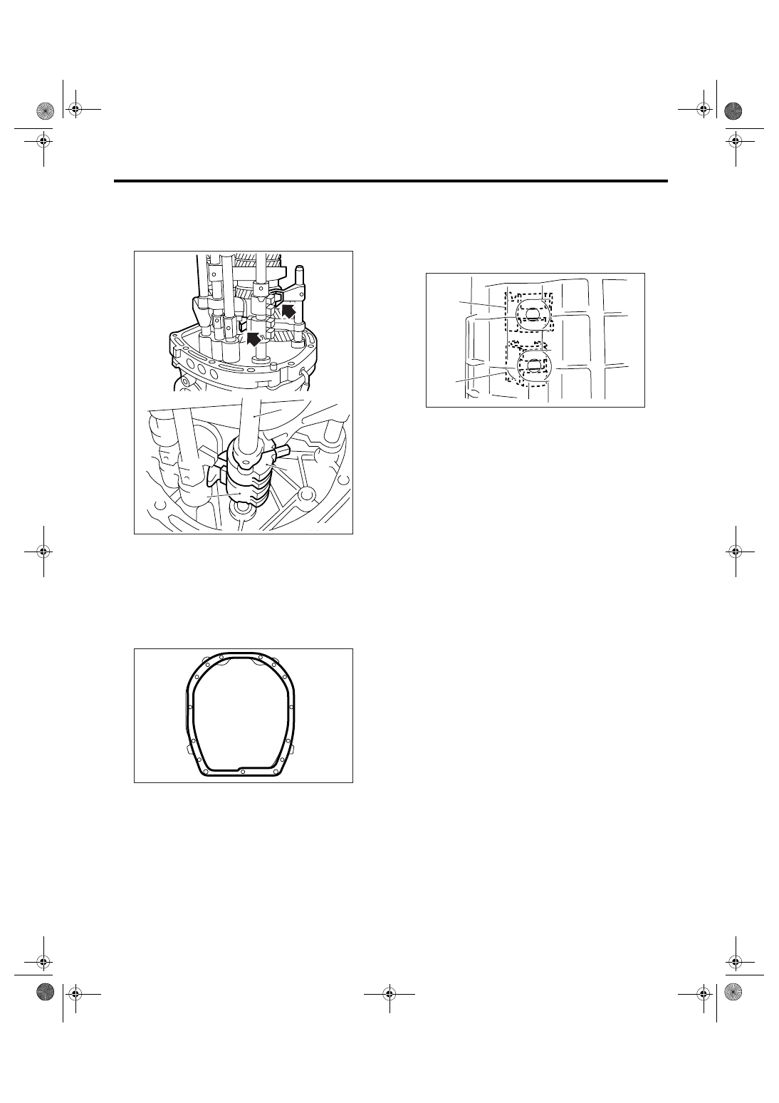
1) Make sure that each shifter fork and interlock
block is shifted to neutral position. If not, shift to the
neutral position.
2) Apply liquid gasket to the adapter plate.
Liquid gasket:
THREE BOND 1215 (Part No. 004403007)
3) Install the transmission case.
4) Make sure the interlock block and reverse inter-
lock block are aligned in neutral position by inspect-
ing through the pilot bolt installation hole. If not
aligned, remove the transmission case, then shift
each shifter fork and interlock block to neutral posi-
tion.
5) Install the pilot bolts and gasket temporarily.
NOTE:
Use a new gasket.
6) Tighten the transmission case with bolts and
nuts.
Tightening torque:
50 N
⋅
m (5.1 kgf-m, 36.9 ft-lb)
7) Tighten the pilot bolts.
Tightening torque:
34 N
⋅
m (3.5 kgf-m, 25.1 ft-lb)
8) Tighten the holder reverse bolt.
Tightening torque:
25 N
⋅
m (2.5 kgf-m, 18.4 ft-lb)
(A) Striking rod
(B) Reverse interlock block
(C) Interlock block
(A)
(C)
(B)
MT-00531
MT-00532
(A) Interlock block
(B) Reverse interlock block
MT-00533
(A)
(B)
6MT-66
MANUAL TRANSMISSION AND DIFFERENTIAL
Transmission Case
9) Install the snap ring, washer and collar of driven
gear assembly.
10) Install the oil pump. <Ref. to 6MT-62, INSTAL-
LATION, Oil Pump.>
11) Install the center differential.f<Ref. to 6MT-60,
INSTALLATION, Center Differential.>
12) Install the transfer driven gear. <Ref. to 6MT-
58, INSTALLATION, Transfer Driven Gear.>
13) Install the extension case. <Ref. to 6MT-47, IN-
STALLATION, Extension Case.>
14) Install the oil pipe, neutral position switch,
back-up light switch and harness. <Ref. to 6MT-42,
INSTALLATION, Oil Pipe.> <Ref. to 6MT-45, IN-
STALLATION, Neutral Position Switch.> <Ref. to
6MT-43, INSTALLATION, Back-up Light Switch.>
15) Install the manual transmission assembly into
vehicle. <Ref. to 6MT-36, INSTALLATION, Manual
Transmission Assembly.>
C: DISASSEMBLY
1) Remove the oil pipe and oil guide.
2) Remove the seal bolt assembly, relief spring and
relief valve.
3) Remove the seal bolt assembly, valve spring
and ball.
(A) Washer
(B) Snap ring
(C) Collar
(D) Washer
(C)
(B)
(A)
(C)
(B)
(D)
(A)
MT-00534
(A) Oil pipe
(B) Oil guide
(A) Seal bolt assembly
(B) Relief valve spring
(C) Relief valve
(A) Seal bolt assembly
(B) Valve spring
(C) Ball
(A)
(B)
MT-00535
(A)
(B)
(C)
MT-00536
(A)
(B)
(C)
MT-00537
Нет комментариевНе стесняйтесь поделиться с нами вашим ценным мнением.
Текст