Subaru Legacy (2005 year). Service manual — part 436
EN(H6DO)(diag)-57
ENGINE (DIAGNOSTICS)
Diagnostics for Engine Starting Failure
C: CHECK POWER SUPPLY AND GROUND LINE OF ENGINE CONTROL MOD-
ULE (ECM)
CAUTION:
After repair or replacement of faulty parts, conduct Clear Memory Mode <Ref. to EN(H6DO)(diag)-41,
OPERATION, Clear Memory Mode.> and Inspection Mode <Ref. to EN(H6DO)(diag)-34, PROCEDURE,
Inspection Mode.>.
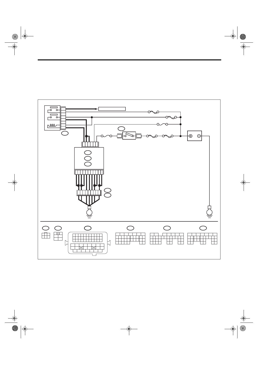
WIRING DIAGRAM:
EN-03490
BATTERY
IGNITION
SWITCH
MAIN RELAY
SBF-6
MAIN SBF
SBF-7
B72
B6
B5
D16
A6
D2
A7
B12
D3
D7
D1
B19
D14
No.12
B47
E2
B21
ECM
E
E
3
6
B134
B135
A:
D: B137
B:
B4
52
37
36
34
12
3
4
1
2
5
6
B47
No.13
B1
35
B134
5
6
7
8
2
1
9
4
3
10
24
22 23
25
11 12 13 14 15
26 27
28
16 17
18 19 20 21
33 34
29
32
30 31
B135
5
6
7
8
2
1
9
4
3
10
24
22 23
25
11 12 13 14 15
26 27
28
16 17 18 19
20 21
29 30 31
32 33
34 35
B137
5
6
7
8
2
1
9
4
3
10
22 23
11 12 13 14 15
24 25
26
16 17
18 19 20 21
27
28 29
30 31
B21
1 2 3 4
12 13 14 15
5 6 7 8
16 17 18 19
9 10 11
20 21 22
23 24 25 26 27 28 29 30 31 32 33
35
34
37
36
39
38
41
40
43
42
44
45
47
46
49
48
51
50
53
52
54
B72
1
3
4 5 6
2
A:
B:
D:
SBF-5
A4
A5
54
3
5
6
4
1
2
TO OXYGEN SENSOR
EN(H6DO)(diag)-58
ENGINE (DIAGNOSTICS)
Diagnostics for Engine Starting Failure
Step
Check
Yes
No
1
CHECK MAIN RELAY.
1) Turn the ignition switch to OFF.
2) Remove the main relay.
3) Connect the battery to main relay terminals
No. 1 and No. 2.
4) Measure the resistance between main relay
terminals.
Terminal
No. 3 — No. 5:
No. 4 — No. 6:
Is the resistance less than 10
Ω?
Replace the main
relay.
2
CHECK GROUND CIRCUIT FOR ECM.
1) Disconnect the connector from ECM.
2) Measure the resistance of harness
between ECM and chassis ground.
Connector & terminal
(B134) No. 4 — Chassis ground:
(B134) No. 5 — Chassis ground:
(B134) No. 6 — Chassis ground:
(B134) No. 7 — Chassis ground:
(B135) No. 1 — Chassis ground:
(B135) No. 4 — Chassis ground:
(B135) No. 12 — Chassis ground:
(B137) No. 1 — Chassis ground:
(B137) No. 2 — Chassis ground:
(B137) No. 3 — Chassis ground:
(B137) No. 7 — Chassis ground:
Is the resistance less than 5
Ω?
Repair the open
circuit of harness
between ECM
connector and
engine grounding
terminal.
3
CHECK INPUT VOLTAGE OF ECM.
Measure the voltage between ECM connector
and chassis ground.
Connector & terminal
(B135) No. 19 (+) — Chassis ground (
−
):
Is the voltage more than 10 V? Go to step 4.
Repair the open or
ground short cir-
cuit of power sup-
ply circuit.
4
CHECK INPUT VOLTAGE OF ECM.
1) Turn the ignition switch to ON.
2) Measure the voltage between ECM con-
nector and chassis ground.
Connector & terminal
(B137) No. 14 (+) — Chassis ground (
−
):
Is the voltage more than 10 V? Go to step 5.
Repair the open or
ground short cir-
cuit of power sup-
ply circuit.
5
CHECK INPUT VOLTAGE OF MAIN RELAY.
Measure the voltage between main relay con-
nector and chassis ground.
Connector & terminal
(B47) No. 1 (+) — Chassis ground (
−
):
Is the voltage more than 10 V? Go to step 6.
Repair the open
circuit of harness
between ECM
connector and
main relay connec-
tor.
6
CHECK INPUT VOLTAGE OF ECM.
1) Connect the connectors to ECM and main
relay.
2) Turn the ignition switch to ON.
3) Measure the voltage between ECM con-
nector and chassis ground.
Connector & terminal
(B137) No. 16 (+) — Chassis ground (
−
):
Is the voltage more than 10 V? Go to step 7.
Repair the open or
ground short cir-
cuit of harness
between ECM
connector and
main relay connec-
tor.
7
CHECK INPUT VOLTAGE OF MAIN RELAY.
Measure the voltage between main relay con-
nector and chassis ground.
Connector & terminal
(B47) No. 5 (+) — Chassis ground (
−
):
(B47) No. 6 (+) — Chassis ground (
−
):
Is the voltage more than 10 V? Go to step 8.
Repair the open or
ground short cir-
cuit of harness of
power supply cir-
cuit.
EN(H6DO)(diag)-59
ENGINE (DIAGNOSTICS)
Diagnostics for Engine Starting Failure
8
CHECK INPUT VOLTAGE OF ECM.
1) Turn the ignition switch to ON.
2) Measure the voltage between ECM con-
nector and chassis ground.
Connector & terminal
(B135) No. 5 (+) — Chassis ground (
−
):
(B135) No. 6 (+) — Chassis ground (
−
):
Is the voltage more than 10 V? Check ignition
control system.
<Ref. to
EN(H6DO)(diag)-
60, IGNITION
CONTROL SYS-
TEM, Diagnostics
for Engine Start-
ing Failure.>
Repair the open or
ground short cir-
cuit of harness
between ECM
connector and
main relay connec-
tor.
Step
Check
Yes
No
EN(H6DO)(diag)-60
ENGINE (DIAGNOSTICS)
Diagnostics for Engine Starting Failure
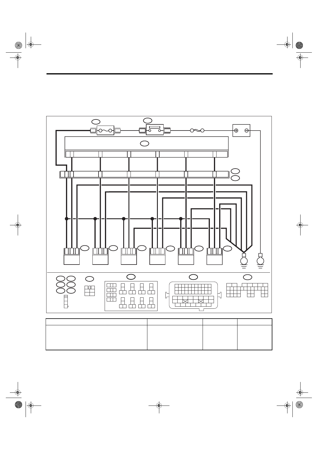
D: IGNITION CONTROL SYSTEM
CAUTION:
After repair or replacement of faulty parts, conduct Clear Memory Mode <Ref. to EN(H6DO)(diag)-41,
OPERATION, Clear Memory Mode.> and Inspection Mode <Ref. to EN(H6DO)(diag)-34, PROCEDURE,
Inspection Mode.>.
WIRING DIAGRAM:
Step
Check
Yes
No
1
CHECK SPARK PLUG CONDITION.
1) Remove the spark plug. <Ref. to
IG(H6DO)-4, REMOVAL, Spark Plug.>
2) Check the spark plug condition. <Ref. to
IG(H6DO)-5, INSPECTION, Spark Plug.>
Is the spark plug’s status OK?
Replace the spark
plug.
E34
E45
E31
E32
E46
E33
1
2
3
ECM
B135
13
17
18
15
14
16
SBF-7
B327
MAIN
RELAY 2
E46
E2
B21
E32
18
14
13
16
17
3
2
3
1
2
E34
3
2
E45
3
2
15
49
1
1
1
E31
IGNITION COIL
No. 1
IGNITION COIL
No. 2
IGNITION COIL
No. 3
IGNITION COIL
No. 4
IGNITION COIL
No. 5
IGNITION COIL
No. 6
3
1
2
E33
3
1
2
EN-03491
1
2
RELAY
HOLDER
B225
B21
1 2 3 4
12 13 14 15
5 6 7 8
16 17 18 19
9 10 11
20 21 22
23 24 25 26 27 28 29 30 31 32 33
35
34
37
36
39
38
41
40
43
42
44
45
47
46
49
48
51
50
53
52
54
9
10
1
2
3
4
5
6
7
8
11 12
14
15 16
13
18
19 20
17
22
23 24
21
38
39 40
37
34
35 36
33
30
31 32
29
26
27 28
25
B225
B135
5
6
7
8
2
1
9
4
3
10
24
22 23
25
11 12 13 14 15
26 27
28
16 17 18 19
20 21
29 30 31
32 33
34 35
B327
3
4
1
2
5
6
E
E
6
4
BATTERY
Нет комментариевНе стесняйтесь поделиться с нами вашим ценным мнением.
Текст