Subaru Legacy (2005 year). Service manual — part 434
EN(H6DO)(diag)-49
ENGINE (DIAGNOSTICS)
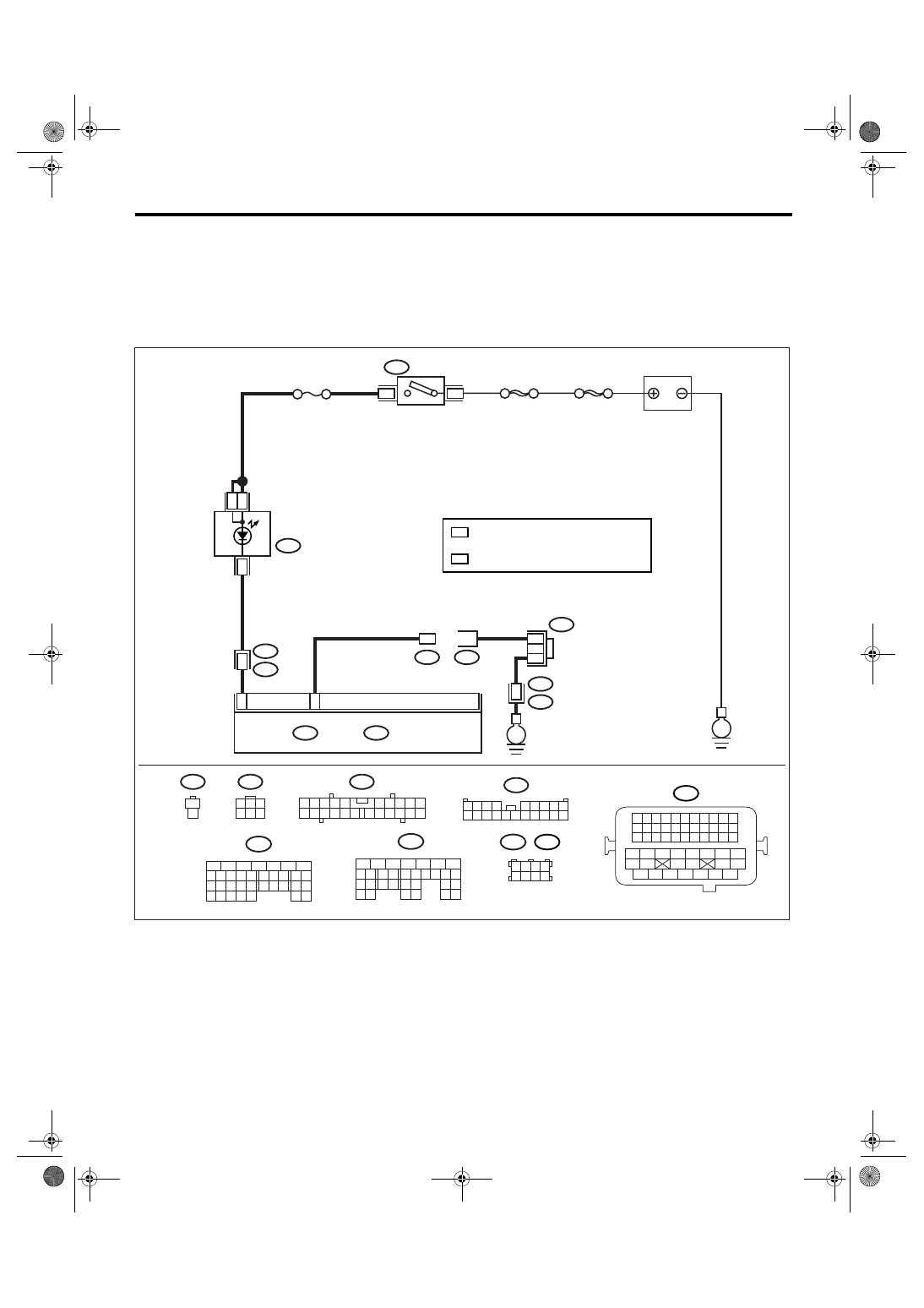
Malfunction Indicator Light
E: MALFUNCTION INDICATOR LIGHT DOES NOT BLINK.
DIAGNOSIS:
• The malfunction indicator light circuit is open or shorted.
• Test mode connector circuit is in open.
TROUBLE SYMPTOM:
Malfunction indicator light does not blink during inspection mode.
WIRING DIAGRAM:
EN-03488
BATTERY
3
B72
B75
B76
IGNITION
SWITCH
i10
COMBINATION
METER
B134
A:
SBF-6
6
A17
D15
ECM
B72
8
MAIN SBF
No.5
*
2
*
1
1
B75
1
2
1
2
16
i3
B38
E
4
3
B137
D:
B134
5
6
7
8
2
1
9
4
3
10
24
22 23
25
11 12 13 14 15
26 27
28
16 17
18 19 20 21
33 34
29
32
30 31
B137
5
6
7
8
2
1
9
4
3
10
22 23
11 12 13 14 15
24 25
26
16 17
18 19 20 21
27
28 29
30 31
A:
D:
1
3
4 5 6
2
i10
B38
1 2 3 4
5 6 7 8 9
10 11 12 13 14 15 16 17 18 19 20
2
1
3 4
6 7 8 9 10
22
21
20
19
18
17
16
15
14
13
12
11
5
1 2 3 4
5 6 7 8
B122
B138
*
E
2
*
1
*
1
*
LHD: B122
RHD: B138
2
B21
1 2 3 4
12 13 14 15
5 6 7 8
16 17 18 19
9 10 11
20 21 22
23 24 25 26 27 28 29 30 31 32 33
35
34
37
36
39
38
41
40
43
42
44
45
47
46
49
48
51
50
53
52
54
B21
E2
36
: TERMINAL No. RANDOM ARRANGEMENT
EN(H6DO)(diag)-50
ENGINE (DIAGNOSTICS)
Malfunction Indicator Light
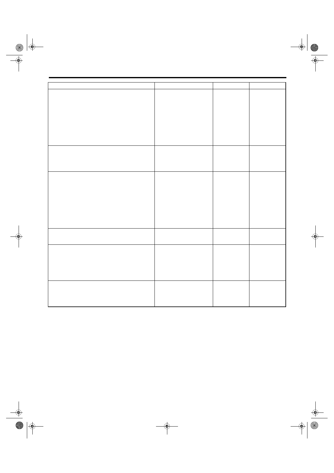
Step
Check
Yes
No
1
CHECK STATUS OF MALFUNCTION INDI-
CATOR LIGHT.
1) Turn the ignition switch to OFF.
2) Disconnect the test mode connectors.
3) Turn the ignition switch to ON. (engine
OFF)
Does the malfunction indicator
light illuminate?
Repair the mal-
function indictor
light circuit. <Ref.
to
EN(H6DO)(diag)-
46, MALFUNC-
TION INDICATOR
LIGHT DOES NOT
COME ON, Mal-
function Indicator
Light.>
2
CHECK HARNESS BETWEEN COMBINA-
TION METER AND ECM CONNECTOR.
1) Turn the ignition switch to OFF.
2) Disconnect the connector from ECM.
3) Turn the ignition switch to ON.
Does the malfunction indicator
light illuminate?
Repair short circuit
of harness
between combina-
tion meter and
ECM connector.
3
CHECK HARNESS BETWEEN TEST MODE
CONNECTOR AND CHASSIS GROUND.
1) Turn the ignition switch to OFF.
2) Disconnect the connector from ECM.
3) Measure the resistance of harness
between test mode connector and chassis
ground.
Connector & terminal
(B76) No. 1 — Chassis ground:
Is the resistance less than 1
Ω?
Repair the har-
ness and connec-
tor.
NOTE:
In this case, repair
the following:
• Open circuit of
harness between
test mode connec-
tor and chassis
ground
4
CHECK POOR CONTACT.
Check poor contact in ECM connector.
Is there poor contact in ECM
connector?
Repair the poor
contact in ECM
connector.
5
CHECK HARNESS BETWEEN ECM AND
TEST MODE CONNECTOR.
1) Connect the test mode connector.
2) Measure the resistance of harness
between ECM and chassis ground.
Connector & terminal
(B137) No. 15 — Chassis ground:
Is the resistance less than 5
Ω?
Repair the open
circuit of harness
between ECM and
test mode connec-
tor.
6
CHECK POOR CONTACT.
Check poor contact in ECM connector.
Is there poor contact in ECM
connector?
Repair the poor
contact in ECM
connector.
Replace the ECM.
<Ref. to
FU(H6DO)-34,
Engine Control
Module (ECM).>
EN(H6DO)(diag)-51
ENGINE (DIAGNOSTICS)
Malfunction Indicator Light
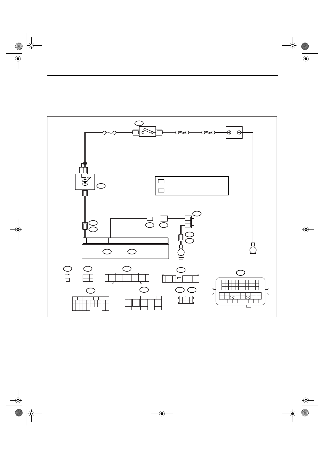
F: MALFUNCTION INDICATOR LIGHT REMAINS BLINKING.
DIAGNOSIS:
Test mode connector circuit is shorted.
TROUBLE SYMPTOM:
Malfunction indicator light blinks when test mode connector is not connected.
WIRING DIAGRAM:
EN-03488
BATTERY
3
B72
B75
B76
IGNITION
SWITCH
i10
COMBINATION
METER
B134
A:
SBF-6
6
A17
D15
ECM
B72
8
MAIN SBF
No.5
*
2
*
1
1
B75
1
2
1
2
16
i3
B38
E
4
3
B137
D:
B134
5
6
7
8
2
1
9
4
3
10
24
22 23
25
11 12 13 14 15
26 27
28
16 17
18 19 20 21
33 34
29
32
30 31
B137
5
6
7
8
2
1
9
4
3
10
22 23
11 12 13 14 15
24 25
26
16 17
18 19 20 21
27
28 29
30 31
A:
D:
1
3
4 5 6
2
i10
B38
1 2 3 4
5 6 7 8 9
10 11 12 13 14 15 16 17 18 19 20
2
1
3 4
6 7 8 9 10
22
21
20
19
18
17
16
15
14
13
12
11
5
1 2 3 4
5 6 7 8
B122
B138
*
E
2
*
1
*
1
*
LHD: B122
RHD: B138
2
B21
1 2 3 4
12 13 14 15
5 6 7 8
16 17 18 19
9 10 11
20 21 22
23 24 25 26 27 28 29 30 31 32 33
35
34
37
36
39
38
41
40
43
42
44
45
47
46
49
48
51
50
53
52
54
B21
E2
36
: TERMINAL No. RANDOM ARRANGEMENT
EN(H6DO)(diag)-52
ENGINE (DIAGNOSTICS)
Malfunction Indicator Light
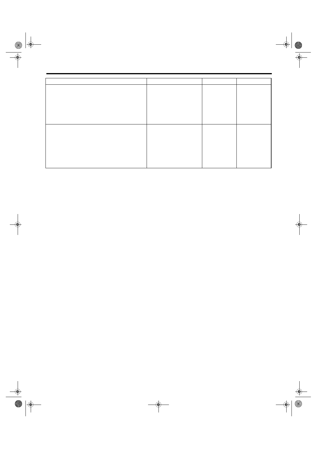
Step
Check
Yes
No
1
CHECK TEST MODE CONNECTOR.
1) Disconnect the test mode connectors.
2) Turn the ignition switch to ON.
Does the malfunction indicator
light blink?
System is in good
order.
NOTE:
Malfunction indica-
tor light blinks
when test mode
connector is con-
nected.
2
CHECK HARNESS BETWEEN ECM CON-
NECTOR AND CHASSIS GROUNDING TER-
MINAL.
1) Turn the ignition switch to OFF.
2) Disconnect the connector from ECM.
3) Measure the resistance of harness
between ECM connector and chassis ground.
Connector & terminal
(B137) No. 15 — Chassis ground:
Is the resistance less than 5
Ω?
Repair the short
circuit of harness
between ECM and
test mode connec-
tor.
Replace the ECM.
<Ref. to
FU(H6DO)-34,
Engine Control
Module (ECM).>
Нет комментариевНе стесняйтесь поделиться с нами вашим ценным мнением.
Текст