Subaru Legacy (2005 year). Service manual — part 648
5MT-39
MANUAL TRANSMISSION AND DIFFERENTIAL
Differential Side Retainer Oil Seal
6. Differential Side Retainer Oil
Seal
A: INSPECTION
Check leakage of gear oil from the differential side
retainer oil seal part. If there is oil leakage, replace
with a new oil seal.
B: REPLACEMENT
1) Lift-up the vehicle.
2) Using TORX
®
BIT T70, remove the drain plug.
Drain gear oil completely.
3) Using TORX
®
BIT T70, tighten the drain plug.
NOTE:
Use a new gasket.
Tightening torque:
70 N
⋅
m (7.1 kgf-m, 51.6 ft-lb)
4) Separate the front drive shaft from transmission.
<Ref. to DS-22, REMOVAL, Front Drive Shaft.>
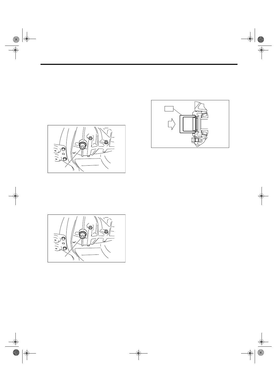
5) Remove the differential side retainer oil seal.
NOTE:
• Be sure to replace the differential side retainer oil
seal after the procedure of removing the front drive
shaft from transmission.
• Using the ST 398527700 puller assembly, re-
move the oil seal. When prying to remove the part
using flat tip screwdriver, be careful not to scratch
the differential side retainer.
6) Using the ST, install the differential side retainer
by slightly tapping with a plastic hammer.
ST
18675AA000
DIFFERENTIAL SIDE OIL
SEAL INSTALLER
NOTE:
Apply oil to the oil seal lips.
7) Install the front drive shaft. <Ref. to DS-22, IN-
STALLATION, Front Drive Shaft.>
ST
28399SA010
FRONT DRIVE SHAFT OIL
SEAL PROTECTOR
8) Lower the vehicle.
9) Pour gear oil through the gauge hole. <Ref. to
5MT-29, REPLACEMENT, Transmission Gear
Oil.>
(A) Drain plug
(A) Drain plug
(A)
MT-01221
(A)
MT-01221
MT-00103
ST
5MT-40
MANUAL TRANSMISSION AND DIFFERENTIAL
Switches and Harness
7. Switches and Harness
A: REMOVAL
1. BACK-UP LIGHT SWITCH AND NEU-
TRAL POSITION SWITCH
1) Disconnect the ground cable from battery.
2) Remove the air intake chamber and cleaner
case. <Ref. to IN(H4SO 2.0)-5, REMOVAL, Air
Cleaner Case.> <Ref. to IN(H4SO 2.0)-7, REMOV-
AL, Air Intake Chamber.>
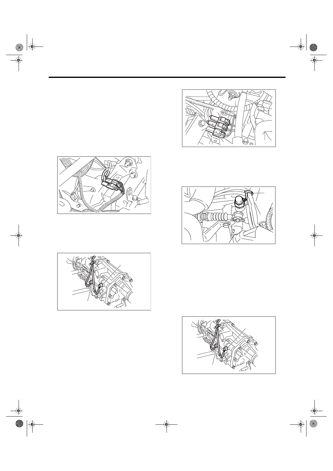
3) Disconnect the connectors of back-up light
switch and neutral position switch.
4) Lift-up the vehicle.
5) Remove the back-up light switch and neutral po-
sition switch with harness.
2. HIGH-LOW SWITCH (DUAL-RANGE
MODEL)
1) Disconnect the ground cable from battery.
2) Remove the air intake chamber and cleaner
case. <Ref. to IN(H4SO 2.0)-5, REMOVAL, Air
Cleaner Case.> <Ref. to IN(H4SO 2.0)-7, REMOV-
AL, Air Intake Chamber.>
3) Disconnect the connector of high-low switch.
4) Remove the high-low switch cable from clamp.
5) Remove the high-low switch.
B: INSTALLATION
1. BACK-UP LIGHT SWITCH AND NEU-
TRAL POSITION SWITCH
1) Install the back-up light switch and neutral posi-
tion switch with harness.
Tightening torque:
25 N
⋅
m (2.5 kgf-m, 18.4 ft-lb)
(A) Neutral position switch connector (Brown)
(B) Back-up light switch connector (Gray)
(A) Neutral position switch (Brown)
(B) Back-up light switch (Gray)
MT-00104
(A)
(B)
MT-00106
(A)
(B)
(A) Neutral position switch (Brown)
(B) Back-up light switch (Gray)
(C) High-low switch (Black)
(A) Clamp
(B) High-low switch
(A) Neutral position switch
(B) Back-up light switch
MT-00107
(B)
(C)
(A)
MT-00108
(B)
(A)
MT-00106
(A)
(B)
5MT-41
MANUAL TRANSMISSION AND DIFFERENTIAL
Switches and Harness
2) Connect the connectors of back-up light switch
and neutral position switch.
3) Install the air intake chamber and cleaner case.
<Ref. to IN(H4SO 2.0)-5, INSTALLATION, Air
Cleaner Case.> <Ref. to IN(H4SO 2.0)-7, INSTAL-
LATION, Air Intake Chamber.>
4) Connect the battery ground cable to battery.
2. HIGH-LOW SWITCH (DUAL-RANGE
MODEL)
1) Install the high-low switch.
Tightening torque:
25 N
⋅
m (2.5 kgf-m, 18.4 ft-lb)
2) Install the high-low switch cable to clamp.
3) Connect the connector of high-low switch.
4) Install the air intake chamber and cleaner case.
<Ref. to IN(H4SO 2.0)-5, INSTALLATION, Air
Cleaner Case.> <Ref. to IN(H4SO 2.0)-7, INSTAL-
LATION, Air Intake Chamber.>
5) Connect the battery ground cable to battery.
C: INSPECTION
1. BACK-UP LIGHT SWITCH
Inspect the back-up light switch. <Ref. to LI-7, IN-
SPECTION, Back-up Light System.>
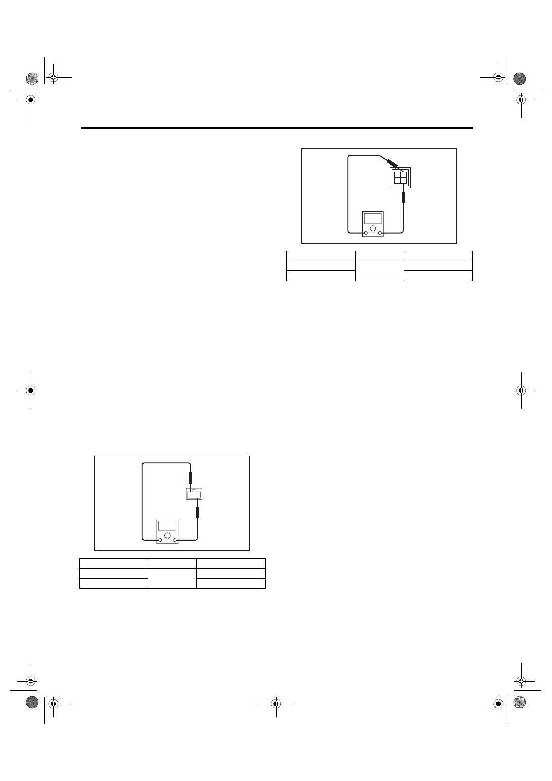
2. NEUTRAL POSITION SWITCH
1) Turn the ignition switch to OFF.
2) Disconnect the connector of neutral position
switch.
3) Measure the resistance between neutral posi-
tion switch terminals.
• Non-turbo model
• Turbo model
4) Replace the faulty parts.
Gear shift position
Terminal No.
Specified resistance
Neutral position
1 and 2
Less than 1
Ω
Other positions
More than 1 M
Ω
MT-00110
1
2
Gear shift position
Terminal No.
Specified resistance
Neutral position
1 and 3
Less than 1
Ω
Other positions
More than 1 M
Ω
MT-00111
1
2
3
4
5MT-42
MANUAL TRANSMISSION AND DIFFERENTIAL
Preparation for Overhaul
8. Preparation for Overhaul
A: PROCEDURE
1) Clean oil, grease, dirt and dust from transmis-
sion.
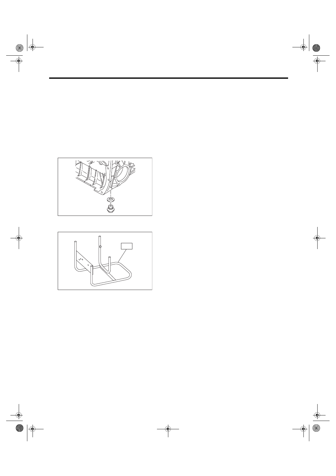
2) Using TORX
®
BIT T70, remove the drain plug to
drain oil. Tighten the engine oil drain plug after
draining.
NOTE:
Use a new gasket.
Tightening torque:
70 N
⋅
m (7.1 kgf-m, 51.6 ft-lb)
3) Attach the transmission to ST.
ST
499937100
TRANSMISSION STAND
4) Rotating parts should be coated with oil prior to
assembly.
5) All disassembled parts, if to be reused, should
be reinstalled in the original positions and direc-
tions.
6) Always use new ones for gaskets, lock washers
and lock nut.
7) Liquid gasket should be used where specified to
prevent leakage.
MT-00097
MT-00115
S T
Нет комментариевНе стесняйтесь поделиться с нами вашим ценным мнением.
Текст