Subaru Legacy (2005 year). Service manual — part 649
5MT-43
MANUAL TRANSMISSION AND DIFFERENTIAL
Transfer Case and Extension Case Assembly
9. Transfer Case and Extension
Case Assembly
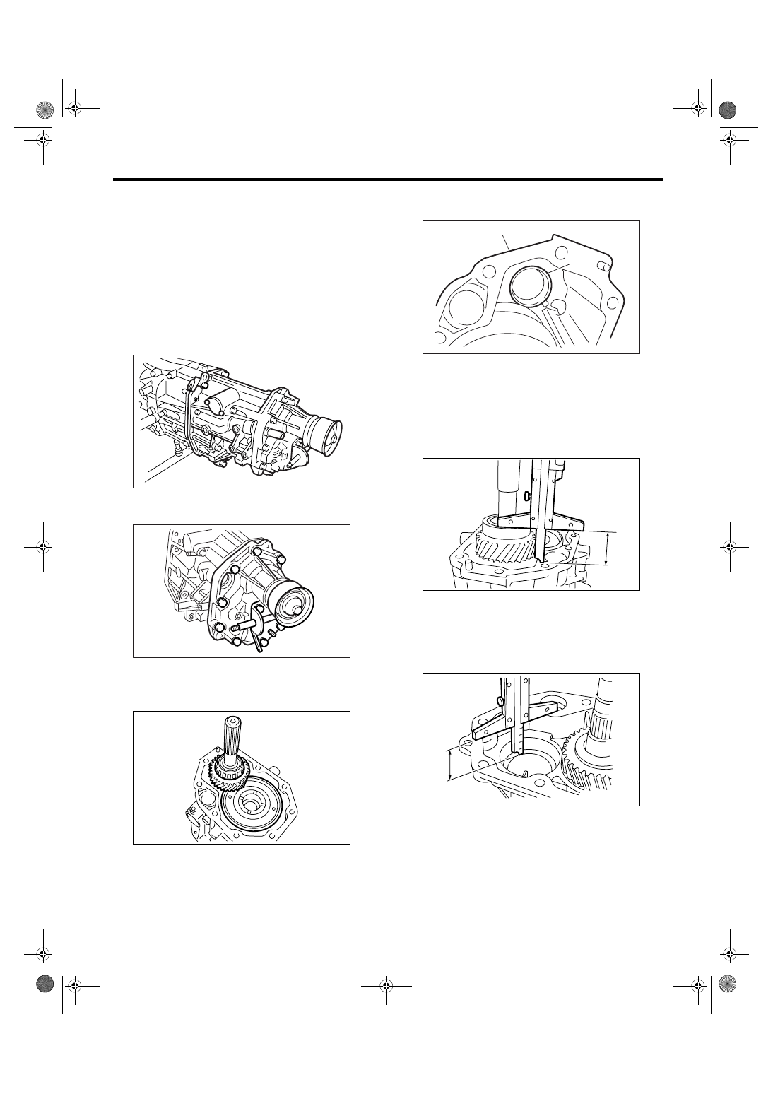
A: REMOVAL
1) Remove the manual transmission assembly
from vehicle. <Ref. to 5MT-30, REMOVAL, Manual
Transmission Assembly.>
2) Remove the back-up light switch and neutral po-
sition switch. <Ref. to 5MT-40, REMOVAL, Switch-
es and Harness.>
3) Remove the transfer case with extension case
assembly.
4) Remove the shifter arm.
5) Remove the extension case assembly.
B: INSTALLATION
1) Install the center differential and transfer driven
gear into transfer case.
2) Remove the bearing outer race from extension
case.
3) While pressing the bearing outer race horizontal-
ly, turn the driven shaft ten rotations.
4) Measure the height “W” between transfer case
and taper roller bearing on the transfer driven gear.
5) Measure the depth “X” on bearing insertion part
of extension case.
NOTE:
Measure with bearing outer race and thrust washer
removed.
6) Calculate the thickness of thrust washer “t” using
following equation.
t = X
− W + 0.2 to 0.3 mm (0.008 to 0.012 in)
7) Select the washer of nearest value in the follow-
ing table:
Standard protrusion amount of taper roller
bearing outer race:
0.2 — 0.3 mm (0.008 — 0.012 in)
MT-00116
MT-00117
MT-00118
(A) Bearing outer race
(B) Extension case
MT-00119
(B)
(A)
MT-00120
W
MT-00121
X
5MT-44
MANUAL TRANSMISSION AND DIFFERENTIAL
Transfer Case and Extension Case Assembly
NOTE:
Be sure that the protrusion amount is within stan-
dard.
8) Fit the thrust washers on transfer drive shaft.
9) Install the bearing outer race into extension
case.
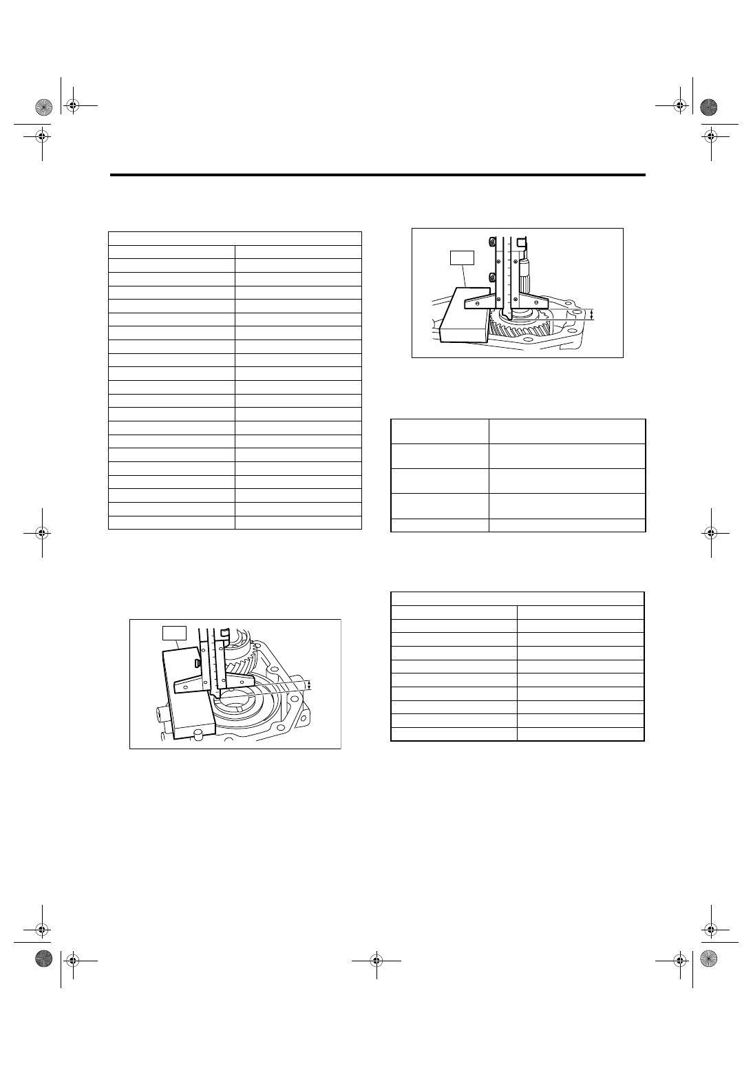
10) Measure the depth “S” between transfer case
and center differential.
ST
398643600
GAUGE
11) Measure the height “T” between extension
case and transfer drive gear.
ST
398643600
GAUGE
12) Calculate the thrust washer “U” using following
equation.
U = 30 mm (1.18 in)
− S − T − 0.15 — 0.35 mm
(0.0059 — 0.0138 in)
13) Select a suitable washer in the following table:
Standard clearance:
0.15 — 0.35 mm (0.0059 — 0.0138 in)
14) Fit the thrust washer on center differential.
Thrust washer (50
× 61 × t)
Part Number
Thickness mm (in)
803050060
0.50 (0.0197)
803050061
0.55 (0.0217)
803050062
0.60 (0.0236)
803050063
0.65 (0.0256)
803050064
0.70 (0.0276)
803050065
0.75 (0.0295)
803050066
0.80 (0.0315)
803050067
0.85 (0.0335)
803050068
0.90 (0.0354)
803050069
0.95 (0.0374)
803050070
1.00 (0.0394)
803050071
1.05 (0.0413)
803050072
1.10 (0.0433)
803050073
1.15 (0.0453)
803050074
1.20 (0.0472)
803050075
1.25 (0.0492)
803050076
1.30 (0.0512)
803050077
1.35 (0.0531)
803050078
1.40 (0.0551)
803050079
1.45 (0.0571)
MT-00122
ST
S
U
mm (in)
Thickness of transfer drive gear
thrust washer
T
mm (in)
Height from end of ST to transfer
drive gear
S
mm (in)
Depth from end of transmission
case to the end of ST
0.15 — 0.35 mm
(0.0059 — 0.0138 in)
Standard clearance between thrust
washer and transfer drive gear.
30 mm (1.18 in)
Thickness of ST
Thrust washer
Part Number
Thickness mm (in)
803036050
0.9 (0.035)
803036054
1.0 (0.039)
803036051
1.1 (0.043)
803036055
1.2 (0.047)
803036052
1.3 (0.051)
803036056
1.4 (0.055)
803036053
1.5 (0.059)
803036057
1.6 (0.063)
803036058
1.7 (0.067)
MT-00123
T
ST
5MT-45
MANUAL TRANSMISSION AND DIFFERENTIAL
Transfer Case and Extension Case Assembly
15) Apply proper amount of liquid gasket to the
transfer case mating surface.
Liquid gasket
THREE BOND 1215 (Part No. 004403007) or
equivalent
16) Install the extension assembly into transfer
case.
Tightening torque:
40 N
⋅
m (4.1 kgf-m, 29.7 ft-lb)
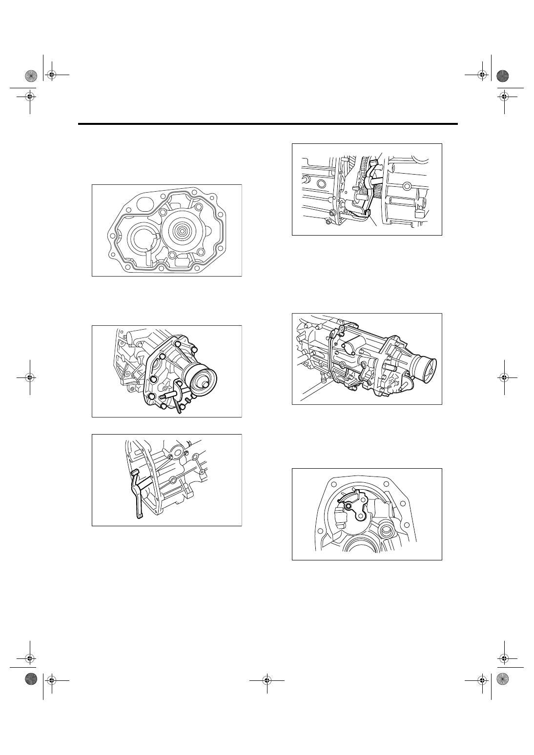
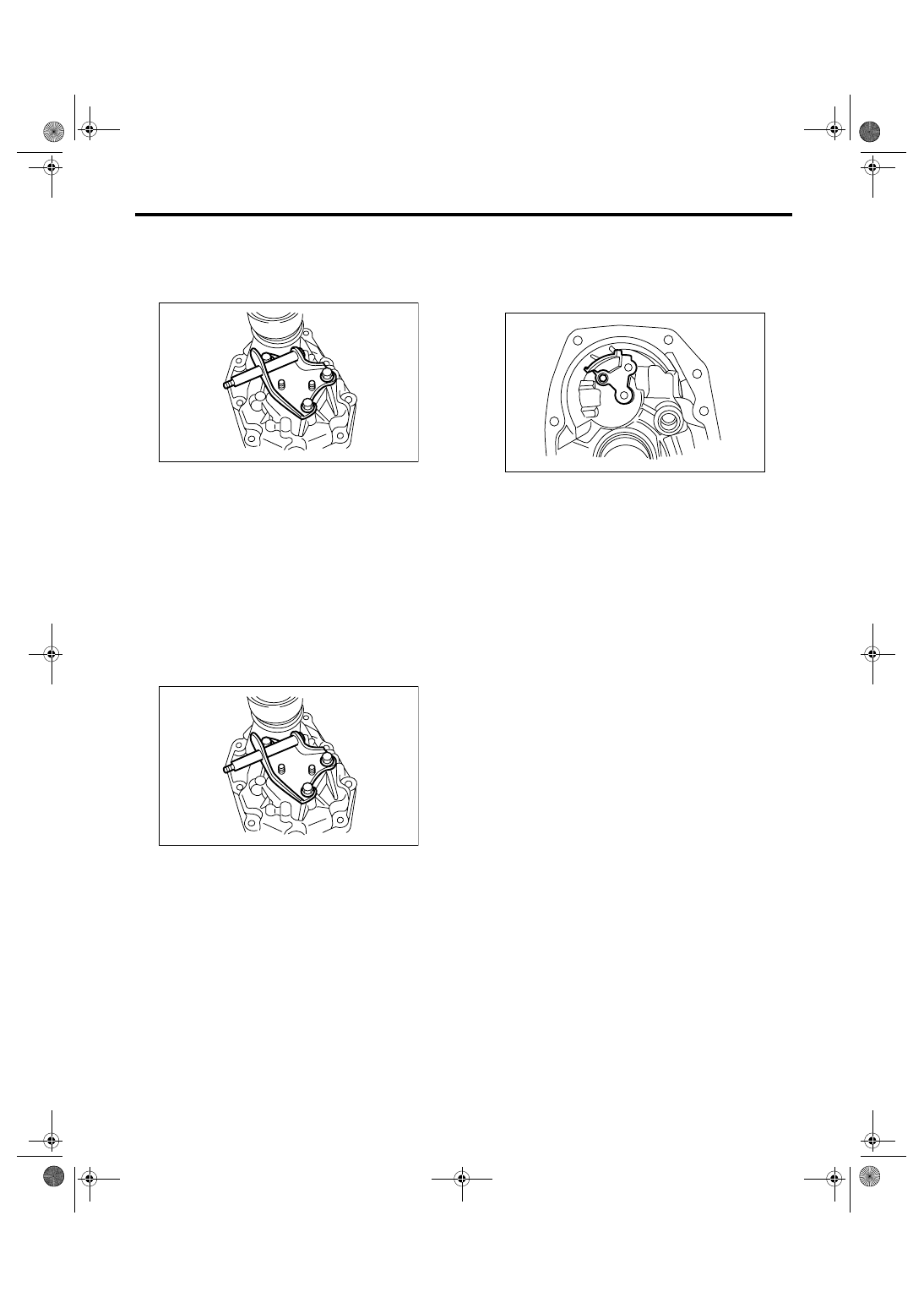
17) Install the shifter arm to transfer case.
18) Hang the shifter arm on 3rd-4th fork rod.
19) Install the transfer case with extension case as-
sembly to transmission case.
Tightening torque:
25 N
⋅
m (2.5 kgf-m, 18.4 ft-lb)
C: DISASSEMBLY
1. TRANSFER CASE
1) Remove the reverse check assembly. <Ref. to
5MT-52, REMOVAL, Reverse Check Sleeve.>
2) Remove the oil guide.
MT-00124
MT-00117
MT-00126
(A) Shifter arm
(B) 3rd-4th fork rod
MT-00127
(A)
(B)
MT-00116
MT-00129
5MT-46
MANUAL TRANSMISSION AND DIFFERENTIAL
Transfer Case and Extension Case Assembly
2. EXTENSION CASE
1) Remove the transfer drive gear assembly. <Ref.
to 5MT-47, REMOVAL, Transfer Drive Gear.>
2) Remove the shift bracket.
3) Remove the oil seal from extension case. <Ref.
to 5MT-38, Oil Seal.>
D: ASSEMBLY
1. EXTENSION CASE
1) Using the ST, install the oil seal to extension
case. <Ref. to 5MT-38, Oil Seal.>
NOTE:
Use a new oil seal.
2) Install the shift bracket to extension case.
Tightening torque:
25 N
⋅
m (2.5 kgf-m, 18.4 ft-lb)
3) Install the transfer drive gear to extension case.
<Ref. to 5MT-47, INSTALLATION, Transfer Drive
Gear.>
2. TRANSFER CASE
1) Install the oil guide to transfer case.
Tightening torque:
6.4 N
⋅
m (0.65 kgf-m, 4.7 ft-lb)
2) Install the reverse check sleeve assembly to
transfer case. <Ref. to 5MT-52, INSTALLATION,
Reverse Check Sleeve.>
MT-00130
MT-00130
MT-00129
Нет комментариевНе стесняйтесь поделиться с нами вашим ценным мнением.
Текст