Subaru Legacy (2005 year). Service manual — part 777
ABS(diag)-73
ABS (DIAGNOSTICS)
Diagnostic Procedure with Diagnostic Trouble Code (DTC)
Y: DTC C0119 G SENSOR OUTPUT VOLTAGE MALFUNCTION
DTC DETECTING CONDITION:
Defective G sensor output signal
TROUBLE SYMPTOM:
ABS does not operate.
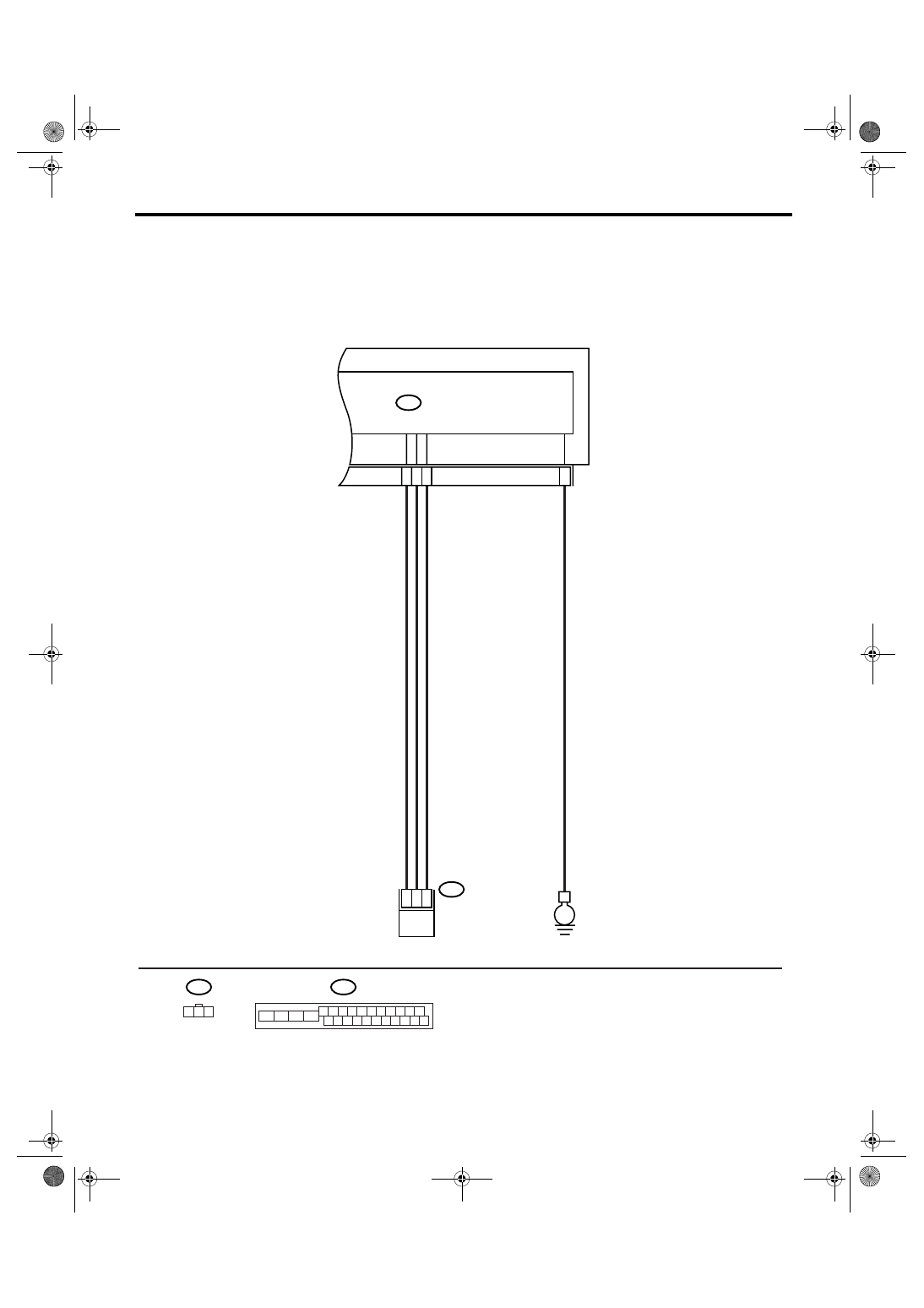
WIRING DIAGRAM:
ABS00419
ABSCM & H/U
B301
B301
10
24
21
15
B292
ABS G SENSOR
E
3
2
1
B292
1 2 3
1 2 3 4 5 6 7 8 9 10 11
16 17 18 19 20 21 22 23 24 25 26
13
12
15
14

ABS(diag)-74
ABS (DIAGNOSTICS)
Diagnostic Procedure with Diagnostic Trouble Code (DTC)
Step
Check
Yes
No
1
WHETHER A WHEEL TURNED FREELY OR
NOT.
Have the wheels been turned
freely when the vehicle is lifted
up or drove on a rolling road?
ABS is normal.
Erase the memory.
2
CHECK OUTPUT OF G SENSOR USING
SUBARU SELECT MONITOR.
1) Select {Current Data Display & Save} in
Subaru Select Monitor.
2) Read the Subaru Select Monitor display.
Is the reading indicated on dis-
play
−1.2 — 1.2 m/s when G
sensor is on a level?
3
CHECK OUTPUT OF G SENSOR USING
SUBARU SELECT MONITOR.
1) Turn the ignition switch to OFF.
2) Remove the console box.
3) Remove the G sensor from vehicle. (Do not
disconnect connector.)
4) Turn the ignition switch to ON.
5) Select {Current Data Display & Save} in
Subaru Select Monitor.
6) Read the Subaru Select Monitor display.
Is the reading indicated on dis-
play 8.1 — 11.2 m/s when G
sensor is inclined forward to
90
°?
Replace G sen-
sor. <Ref. to ABS-
18, G Sensor.>
4
CHECK OUTPUT OF G SENSOR USING
SUBARU SELECT MONITOR.
Read the Subaru Select Monitor display.
Is the reading indicated on dis-
play
−8.1 — −11.2 m/s when G
sensor is inclined backward to
90
°?
Replace G sen-
sor. <Ref. to ABS-
18, G Sensor.>
5
CHECK POOR CONTACT IN CONNECTOR.
Turn the ignition switch to OFF.
Is there poor contact in con-
nector between ABSCM&H/U
and G sensor?
Repair the con-
nector.
6
CHECK ABSCM&H/U.
1) Connect all the connectors.
2) Perform clear memory mode.
3) Perform the inspection mode.
4) Read the DTC.
Is the same DTC displayed?
Replace the
ABSCM only.
<Ref. to ABS-8,
REPLACEMENT,
ABS Control Mod-
ule and Hydraulic
Control Unit
(ABSCM&H/U).>
7
CHECK ANY OTHER DTC ON DISPLAY.
Is any other DTC displayed?
Inspect the DTC
using “List of Diag-
nostic Trouble
Code (DTC)”.
<Ref. to
ABS(diag)-38, List
of Diagnostic Trou-
ble Code (DTC).>
Temporary poor
contact occurs.
8
CHECK OPEN CIRCUIT IN G SENSOR OUT-
PUT HARNESS AND GROUND HARNESS.
1) Turn the ignition switch to OFF.
2) Disconnect the connector from ABSCM&H/
U.
3) Measure the resistance between
ABSCM&H/U connector terminals.
Connector & terminal
(B301) No. 21 — No. 10:
Is the resistance 1.8 — 2.4
k
Ω?
Repair the har-
ness connector
between G sensor
and ABSCM&H/U.
9
CHECK GROUND SHORT OF HARNESS.
Measure the resistance between ABSCM&H/U
connector and chassis ground.
Connector & terminal
(B301) No. 21 — Chassis ground:
Is the resistance more than 1
M
Ω?
Repair the har-
ness connector
between G sensor
and ABSCM&H/U.

ABS(diag)-75
ABS (DIAGNOSTICS)
Diagnostic Procedure with Diagnostic Trouble Code (DTC)
10
CHECK G SENSOR.
1) Remove the console box.
2) Remove the G sensor from vehicle.
3) Connect the connector to G sensor.
4) Connect the connector to ABSCM&H/U.
5) Turn the ignition switch to ON.
6) Measure the voltage between G sensor
connector terminals.
Connector & terminal
(B292) No. 2 (+) — No. 3 (
−
):
Is the voltage 2.1 — 2.5 V
when G sensor is on a level?
Replace G sen-
sor. <Ref. to ABS-
18, G Sensor.>
11
CHECK G SENSOR.
Measure the voltage between G sensor con-
nector terminals.
Connector & terminal
(B292) No. 2 (+) — No. 3 (
−
):
Is the voltage 3.6 — 4.1 V
when G sensor is inclined for-
wards to 90
°?
Replace G sen-
sor. <Ref. to ABS-
18, G Sensor.>
12
CHECK G SENSOR.
Measure the voltage between G sensor con-
nector terminals.
Connector & terminal
(B292) No. 2 (+) — No. 3 (
−
):
Is the voltage 0.5 — 1.0 V
when G sensor is inclined
backward to 90
°?
Replace G sen-
sor. <Ref. to ABS-
18, G Sensor.>
13
CHECK ABSCM&H/U.
1) Turn the ignition switch to OFF.
2) Connect all the connectors.
3) Perform clear memory mode.
4) Perform the inspection mode.
5) Read the DTC.
Is the same DTC displayed?
Replace the
ABSCM only.
<Ref. to ABS-8,
REPLACEMENT,
ABS Control Mod-
ule and Hydraulic
Control Unit
(ABSCM&H/U).>
14
CHECK ANY OTHER DTC ON DISPLAY.
Is any other DTC displayed?
Inspect the DTC
using “List of Diag-
nostic Trouble
Code (DTC)”.
<Ref. to
ABS(diag)-38, List
of Diagnostic Trou-
ble Code (DTC).>
Temporary poor
contact occurs.
Step
Check
Yes
No
ABS(diag)-76
ABS (DIAGNOSTICS)
General Diagnostic Table
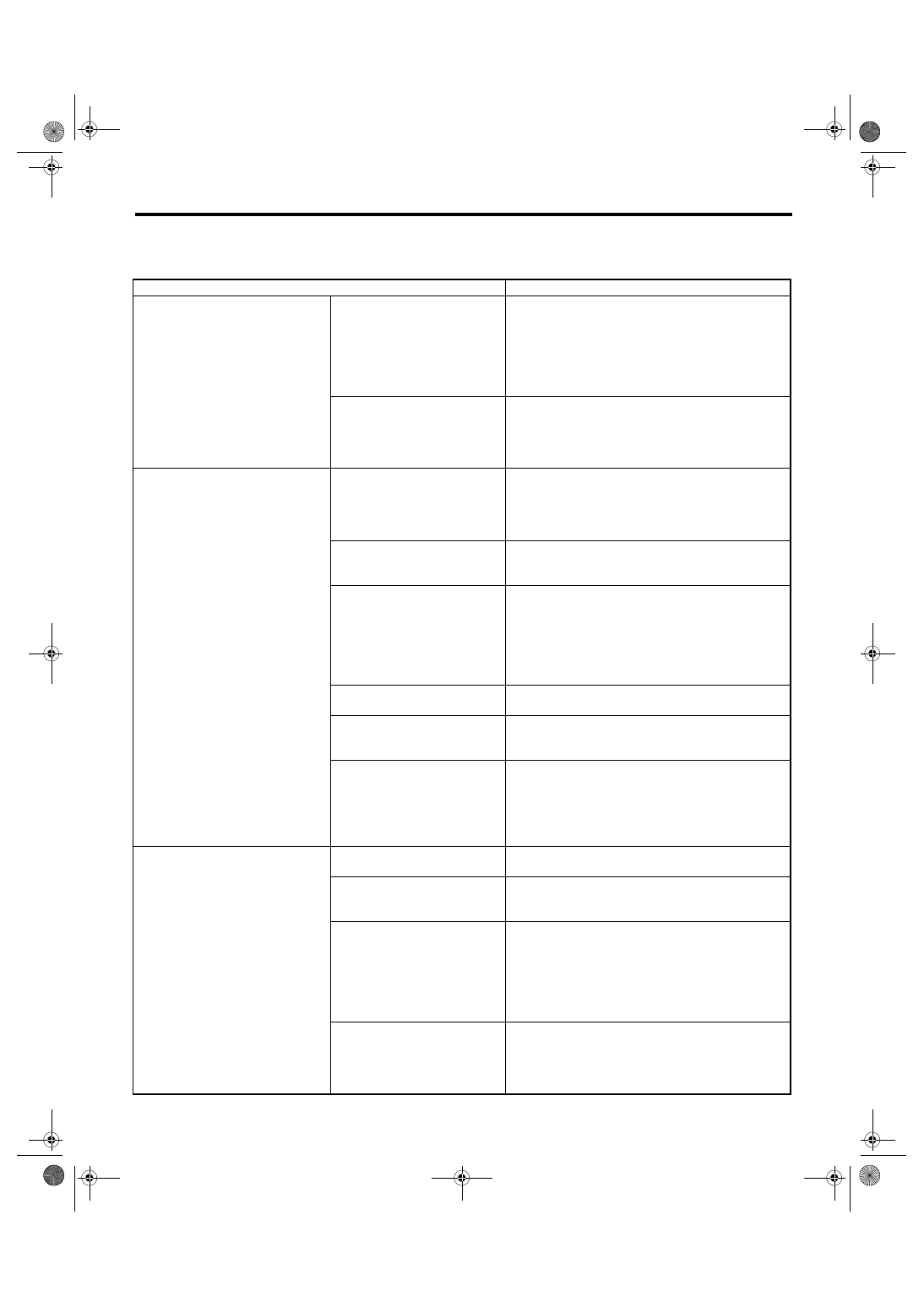
13.General Diagnostic Table
A: INSPECTION
Symptom
Problem parts
Vehicle instability during braking
Vehicle is pulled to either right or
left side.
• ABSCM&H/U (solenoid valve)
• ABS wheel speed sensor
• Brake (caliper, piston and pads)
• Wheel Alignment
• Tire specifications, tire wear and air pressures
• Incorrect wiring or piping connections
• Road surface (uneven, camber)
Vehicle spins.
• ABSCM&H/U (solenoid valve)
• ABS wheel speed sensor
• Brake (pads)
• Tire specifications, tire wear and air pressures
• Incorrect wiring or piping connections
Poor brake performance
Long braking/stopping distance
• ABSCM&H/U (solenoid valve)
• Brake (pads)
• Air in brake line
• Tire specifications, tire wear and air pressures
• Incorrect wiring or piping connections
Wheel locks.
• ABSCM&H/U (solenoid valve, motor)
• ABS wheel speed sensor
• Incorrect wiring or piping connections
Brake drag
• ABSCM&H/U (solenoid valve)
• ABS wheel speed sensor
• Master cylinder
• Brake (caliper and piston)
• Parking Brake
• Axle and wheels
• Brake pedal play
Long brake pedal stroke
• Air in brake line
• Brake pedal play
Vehicle vertical pitching
• Suspension play or fatigue (reduced damping)
• Incorrect wiring or piping connections
• Road surface (uneven)
Unstable or uneven braking
• ABSCM&H/U (solenoid valve)
• ABS wheel speed sensor
• Brake (caliper, piston and pads)
• Tire specifications, tire wear and air pressures
• Incorrect wiring or piping connections
• Road surface (uneven)
Vibration and/or noise
(while driving on slippery roads)
Excessive pedal vibration
• Incorrect wiring or piping connections
• Road surface (uneven)
Noise from ABSCM&H/U
• ABSCM&H/U (mount bushing)
• ABS wheel speed sensor
• Brake line
Noise from front of vehicle
• ABSCM&H/U (mount bushing)
• ABS wheel speed sensor
• Master cylinder
• Brake (caliper, piston, pads and rotor)
• Brake line
• Brake booster and check valve
• Suspension play or fatigue
Noise from rear of vehicle
• ABS wheel speed sensor
• Brake (caliper, piston, pads and rotor)
• Parking Brake
• Brake line
• Suspension play or fatigue
Нет комментариевНе стесняйтесь поделиться с нами вашим ценным мнением.
Текст