Subaru Legacy (2005 year). Service manual — part 775
ABS(diag)-65
ABS (DIAGNOSTICS)
Diagnostic Procedure with Diagnostic Trouble Code (DTC)
Step
Check
Yes
No
1
CHECK INPUT VOLTAGE OF ABSCM&H/U.
1) Turn the ignition switch to OFF.
2) Disconnect the connector from ABSCM&H/
U.
3) Run the engine at idle.
4) Measure the voltage between ABSCM&H/
U connector and chassis ground.
Connector & terminal
(B301) No. 18 (+) — Chassis ground (
−
):
(B301) No. 14 (+) — Chassis ground (
−
):
Is the voltage 10 — 15 V?
Repair the har-
ness connector
between battery
and ABSCM&H/U.
2
CHECK GROUND CIRCUIT OF ABSCM&H/U.
1) Turn the ignition switch to OFF.
2) Measure the resistance between
ABSCM&H/U connector and chassis ground.
Connector & terminal
(B301) No. 15 — Chassis ground:
Is the resistance less than 0.5
Ω?
Repair the
ABSCM&H/U
ground harness.
3
CHECK VALVE RELAY IN ABSCM&H/U.
Measure the resistance between ABSCM&H/U
terminals.
Terminals
No. 14 — No. 15:
Is the resistance more than 1
M
Ω?
Replace the
ABSCM only.
<Ref. to ABS-8,
REPLACEMENT,
ABS Control Mod-
ule and Hydraulic
Control Unit
(ABSCM&H/U).>
4
CHECK POOR CONTACT IN CONNECTOR. Is there poor contact in con-
nector between generator, bat-
tery and ABSCM&H/U?
Repair the con-
nector.
5
CHECK ABSCM&H/U.
1) Connect all the connectors.
2) Perform clear memory mode.
3) Perform the inspection mode.
4) Read the DTC.
Is the same DTC displayed?
Replace the
ABSCM only.
<Ref. to ABS-8,
REPLACEMENT,
ABS Control Mod-
ule and Hydraulic
Control Unit
(ABSCM&H/U).>
6
CHECK ANY OTHER DTC ON DISPLAY.
Is any other DTC displayed?
Inspect the DTC
using “List of Diag-
nostic Trouble
Code (DTC)”.
<Ref. to
ABS(diag)-38, List
of Diagnostic Trou-
ble Code (DTC).>
Temporary poor
contact occurs.
ABS(diag)-66
ABS (DIAGNOSTICS)
Diagnostic Procedure with Diagnostic Trouble Code (DTC)
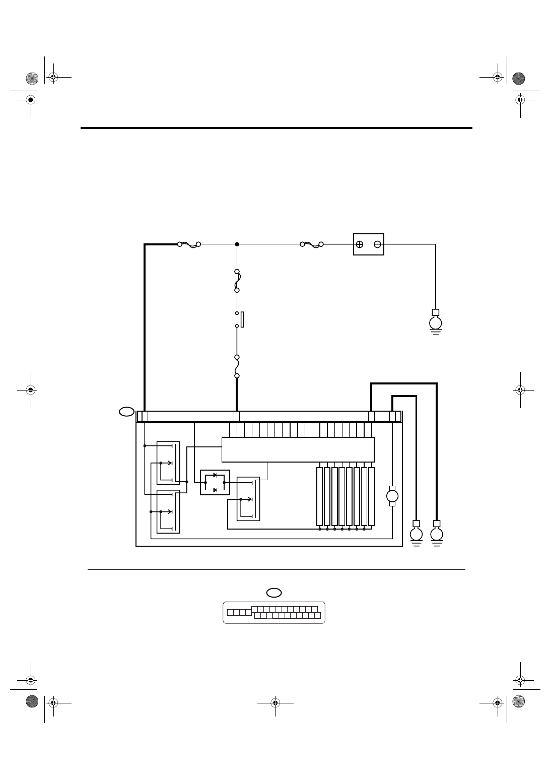
V: DTC C0111 MOTOR/MOTOR RELAY MALFUNCTION
DTC DETECTING CONDITION:
• Defective motor
• Defective motor relay
• Defective harness connector
TROUBLE SYMPTOM:
ABS does not operate.
WIRING DIAGRAM:
VALVE
RELAY
ABS00741
B301
E
E
13
15
12
ABSCM & H/U
18
M
MAIN SBF
SBF-6
No.33
E
SBF-1
B301
7 8 9 10 11
6
5
4
1
15
14
13
12
2 3
22 23 24 25 26
21
20
19
16 17 18
BATTERY
IGNITION
SWITCH
MOTOR RELAY
SOLENOID
VALVE
PUMP MOTOR
FL INLET
RL INLET
FR INLET
RR INLET
FL OUTLET
RL OUTLET
FR OUTLET
RR OUTLET
ABS(diag)-67
ABS (DIAGNOSTICS)
Diagnostic Procedure with Diagnostic Trouble Code (DTC)
Step
Check
Yes
No
1
CHECK INPUT VOLTAGE OF ABSCM&H/U.
1) Turn the ignition switch to OFF.
2) Disconnect the connector from ABSCM&H/
U.
3) Turn the ignition switch to ON.
4) Measure the voltage between ABSCM&H/
U connector and chassis ground.
Connector & terminal
(B301) No. 13 (+) — Chassis ground (
−
):
Is the voltage 10 — 15 V?
Repair the har-
ness connector
between battery
and ABSCM&H/U.
2
CHECK GROUND CIRCUIT OF MOTOR.
1) Turn the ignition switch to OFF.
2) Measure the resistance between
ABSCM&H/U connector and chassis ground.
Connector & terminal
(B301) No. 12 — Chassis ground:
Is the resistance less than 0.5
Ω?
Repair the
ABSCM&H/U
ground harness.
3
CHECK INPUT VOLTAGE OF ABSCM&H/U.
1) Run the engine at idle.
2) Measure the voltage between ABSCM&H/
U connector and chassis ground.
Connector & terminal
(B301) No. 18 (+) — Chassis ground (
−
):
Is the voltage 10 — 15 V?
Repair the har-
ness connector
between battery,
ignition switch and
ABSCM&H/U.
4
CHECK GROUND CIRCUIT OF ABSCM&H/U.
1) Turn the ignition switch to OFF.
2) Measure the resistance between
ABSCM&H/U connector and chassis ground.
Connector & terminal
(B301) No. 15 — Chassis ground:
Is the resistance less than 0.5
Ω?
Repair the
ABSCM&H/U
ground harness.
5
CHECK POOR CONTACT IN CONNECTOR.
Turn the ignition switch to OFF.
Is there poor contact in con-
nector between generator, bat-
tery and ABSCM&H/U?
Repair the con-
nector.
6
CHECK ABSCM&H/U.
1) Connect all the connectors.
2) Perform clear memory mode.
3) Perform the inspection mode.
4) Read the DTC.
Is the same DTC displayed?
Replace
ABSCM&H/U.
<Ref. to ABS-6,
ABS Control Mod-
ule and Hydraulic
Control Unit
(ABSCM&H/U).>
7
CHECK ANY OTHER DTC ON DISPLAY.
Is any other DTC displayed?
Inspect the DTC
using “List of Diag-
nostic Trouble
Code (DTC)”.
<Ref. to
ABS(diag)-38, List
of Diagnostic Trou-
ble Code (DTC).>
Temporary poor
contact occurs.
NOTE:
Though ABS warn-
ing light remains to
illuminate at this
time, it is normal.
Drive the vehicle at
more than 12 km/h
(7 MPH) in order to
make ABS warning
light go off. Be sure
to drive the vehicle
and check the
warning light goes
off.
ABS(diag)-68
ABS (DIAGNOSTICS)
Diagnostic Procedure with Diagnostic Trouble Code (DTC)
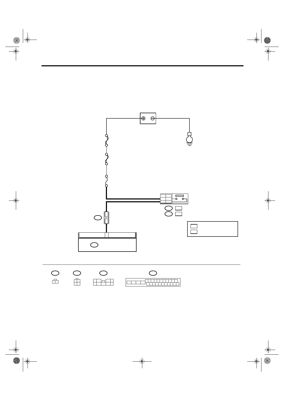
W: DTC C0116 FAULTY STOP LIGHT SWITCH
DTC DETECTING CONDITION:
Defective stop light switch
WIRING DIAGRAM:
ABS00688
MAIN SBF
SBF-2
No.8
B301
2
3
E
20
ABSCM & H/U
B64 : OC
WC
1
2
OC
B65 : WC
9
5
WC
OC
: WITH CRUISE CONTROL
: WITHOUT CRUISE CONTROL
B159
STOP LIGHT SWITCH
BATTERY
B64
1 2 3 4 5 6 7 8 9 10 11
16 17 18 19 20 21 22 23 24 25 26
13
12
15
14
9
4
7
6
2
1
5
3
8
1 2
B159
B301
B65
1
3 4
2
Нет комментариевНе стесняйтесь поделиться с нами вашим ценным мнением.
Текст