Subaru Legacy (2005 year). Service manual — part 748
DS-7
DRIVE SHAFT SYSTEM
General Description
C: CAUTION
• Wear work clothing, including a cap, protective
goggles, and protective shoes during operation.
• Remove contamination including dirt and corro-
sion before removal, installation or disassembly.
• Keep the disassembled parts in order and pro-
tect them from dust and dirt.
• Before removal, installation or disassembly, be
sure to clarify the failure. Avoid unnecessary re-
moval, installation, disassembly and replacement.
• Be careful not to burn yourself, because each
part on the vehicle is hot after running.
• Use SUBARU genuine grease etc. or the equiv-
alent. Do not mix grease, etc. with that of another
grade or from other manufacturers.
• Be sure to tighten fasteners including bolts and
nuts to the specified torque.
• Place shop jacks or rigid racks at the specified
points.
• Apply grease onto sliding or revolution surfaces
before installation.
• Before installing snap rings, apply sufficient
amount of grease to avoid damage and deforma-
tion.
• Before securing a part on a vise, place cushion-
ing material such as wood blocks, aluminum plate,
or shop cloth between the part and the vise.
D: PREPARATION TOOL
1. SPECIAL TOOL
ILLUSTRATION
TOOL NUMBER
DESCRIPTION
REMARKS
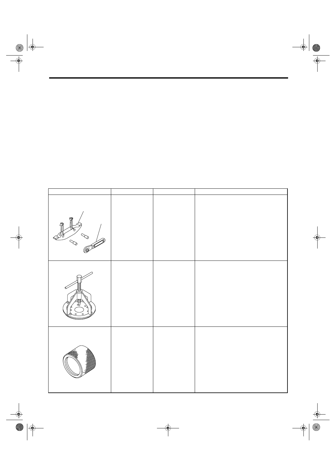
925091000
BAND TIGHTENING
TOOL
Used for tightening boot band.
(A) Jig for band
(B) Ratchet wrench
926470000
AXLE SHAFT
PULLER
Used for removing axle shaft.
18675AA000
DIFFERENTIAL
SIDE OIL SEAL
INSTALLER
Used for installing differential side retainer oil
seal.
ST-925091000
(A)
(B)
ST-926470000
ST18675AA000
DS-8
DRIVE SHAFT SYSTEM
General Description
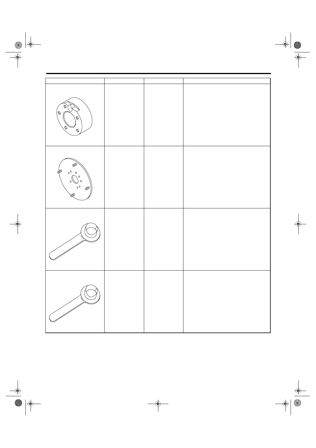
927080000
HUB STAND
Used for assembling hub bolt in hub.
927140000
AXLE SHAFT
PULLER PLATE
Same as plate 2 included in AXLE SHAFT
PULLER (926470000).
28099PA090
OIL SEAL PROTEC-
TOR
• Used for installing rear drive shaft into rear dif-
ferential.
• For protecting oil seal.
28399SA010
OIL SEAL PROTEC-
TOR
• Used for installing front drive shaft into front
differential.
• For protecting oil seal.
ILLUSTRATION
TOOL NUMBER
DESCRIPTION
REMARKS
ST-927080000
ST-927140000
ST28099PA090
ST28399SA010
DS-9
DRIVE SHAFT SYSTEM
General Description
2. GENERAL TOOL
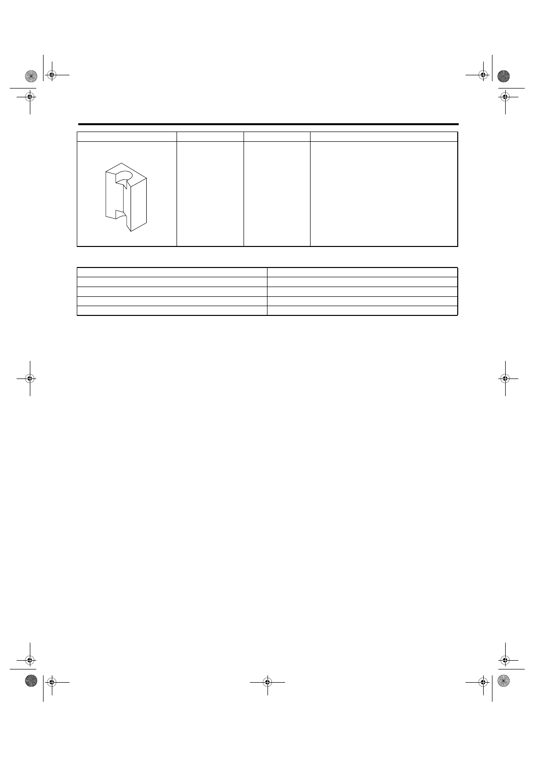
28399AG000
(Newly adopted tool)
HUB STAND
Used for extracting hub bolt.
DESCRIPTION
REMARKS
Puller
Used for removing ball joint from knuckle arm.
Dial gauge
Used for inspecting propeller shaft run-out.
Extension cap
Used for preventing leak of gear oil or ATF.
Bar
Used for extracting drive shaft.
ILLUSTRATION
TOOL NUMBER
DESCRIPTION
REMARKS
ST28399AG000
DS-10
DRIVE SHAFT SYSTEM
Propeller Shaft
2. Propeller Shaft
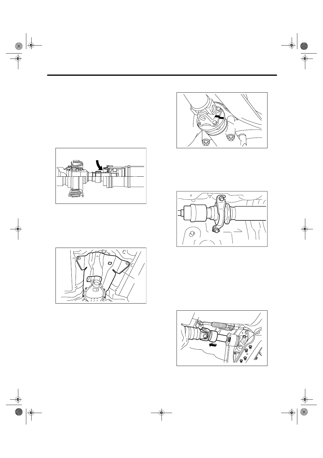
A: REMOVAL
NOTE:
• Before removing propeller shaft, wrap metal
parts with a cloth or rubber material.
• In case of DOJ type, before removing propeller
shaft, wrap metal parts (installed at the rubber boot
of center DOJ) with a cloth or rubber material, as
shown in the figure. Rubber boot may be damaged
due to interference with adjacent metal parts while
bending the DOJ during removal.
1) Disconnect the ground cable from battery.
2) Shift the select lever or gear shift lever to neutral.
3) Release the parking brake.
4) Lift-up the vehicle.
5) Remove the center exhaust pipe.
6) Remove the rear exhaust pipe and muffler.
7) Remove the heat shield cover.
8) Make matching marks on the flange yoke and
rear differential before removal.
9) Remove the three bolts which hold propeller
shaft to rear differential.
10) Remove the remaining bolt.
11) Remove the two bolts which hold center bear-
ing to vehicle body.
12) Remove the propeller shaft from transmission.
CAUTION:
• Be careful not to damage oil seals and fric-
tional surface of sleeve yoke.
• Cover the center exhaust pipe with a cloth to
keep off any ATF or oil spilled from transmis-
sion when removing propeller shaft.
NOTE:
Use a container to catch ATF or oil flowing from
propeller shaft.
(A) Heat shield cover
DS-00239
DS-00230
(A)
(A) Alignment mark
DS-00028
(A)
DS-00141
DS-00030
S301.fm 10 ページ 2007年12月3日 月曜日 午後1時44分
Нет комментариевНе стесняйтесь поделиться с нами вашим ценным мнением.
Текст