Subaru Legacy (2005 year). Service manual — part 749
DS-11
DRIVE SHAFT SYSTEM
Propeller Shaft
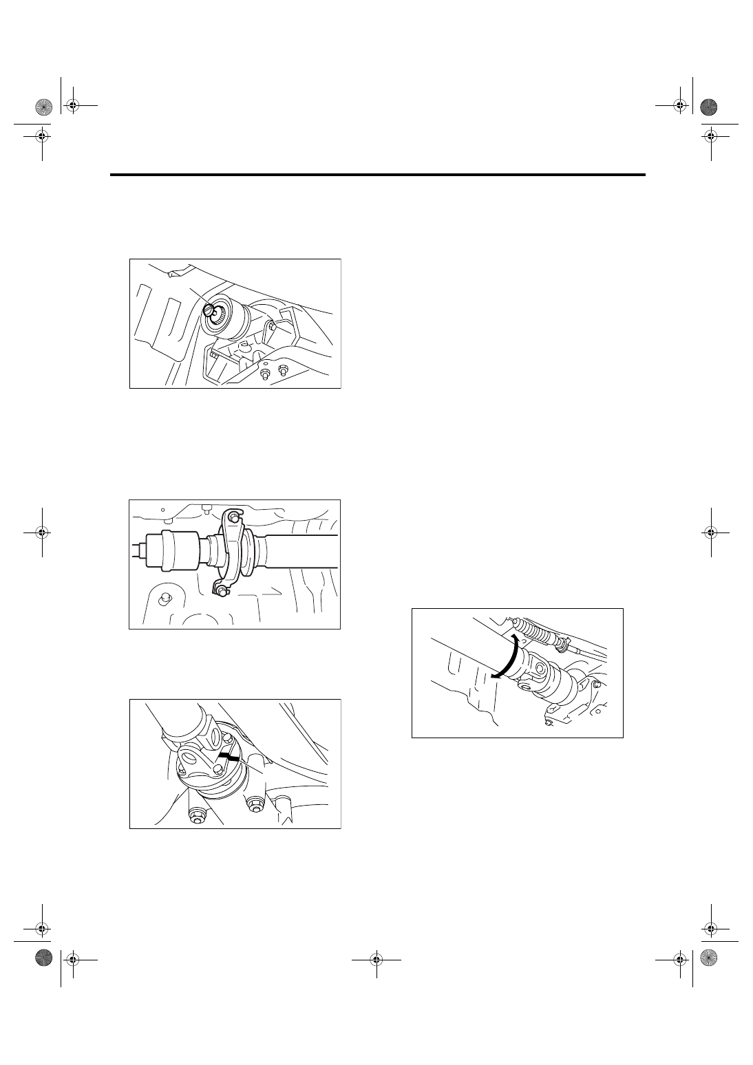
13) Install the extension cap to transmission.
NOTE:
If extension cap is not available, place vinyl bag
over opening and fasten with string to prevent gear
oil or ATF from leaking.
B: INSTALLATION
1) Insert the sleeve yoke into the transmission and
attach center bearing to body.
Tightening torque:
52 N
⋅
m (5.3 kgf-m, 38.3 ft-lb)
2) Align the matching marks and connect the flange
yoke and rear differential.
Tightening torque:
31 N
⋅
m (3.2 kgf-m, 23.1 ft-lb)
3) Install the heat shield cover.
4) Install the center exhaust pipe.
5) Install the rear exhaust pipe and muffler.
6) Lower the vehicle.
7) Connect the battery ground cable to battery.
C: INSPECTION
NOTE:
Do not disassemble propeller shaft. Check the fol-
lowing and replace if necessary.
• Tube surface for dents of cracks
• Splines for deformation or abnormal wear
• Joints for non-smooth operation or abnormal
noise
• Center bearing for free play, noise or non-
smooth operation.
• Oil seals for abnormal wear or damage
• Center bearing for breakage
Check the following points with propeller shaft in-
stalled in vehicle.
1. JOINTS AND CONNECTIONS
1) Remove the center exhaust pipe.
2) Remove the heat shield cover.
3) Check for any looseness of the flange yoke
mounting bolts which connect to rear differential
and center bearing bracket mounting bolts.
2. SPLINES AND BEARING
1) Remove the center exhaust pipe.
2) Remove the rear exhaust pipe and muffler.
3) Remove the heat shield cover.
4) Turn the propeller shaft by hand to see if abnor-
mal free play exists at splines. Also move yokes to
see if abnormal free play exists at spiders and
bearings.
3. RUNOUT OF PROPELLER SHAFT
1) Remove the center exhaust pipe.
2) Remove the rear exhaust pipe and muffler.
3) Remove the heat shield cover.
4) Set the dial gauge with its indicator stem at cen-
ter of propeller shaft tube.
(A) Extension cap
(A) Alignment mark
DS-00031
(A)
DS-00141
DS-00028
(A)
DS-00035
DS-12
DRIVE SHAFT SYSTEM
Propeller Shaft
5) Turn the propeller shaft slowly by hands to check
for “runout” of propeller shaft.
Runout:
Service limit 0.6 mm (0.024 in)
4. CENTER BEARING FREE PLAY
1) Remove the front and center exhaust pipe.
2) Remove the rear exhaust pipe and muffler.
3) Remove the heat shield cover.
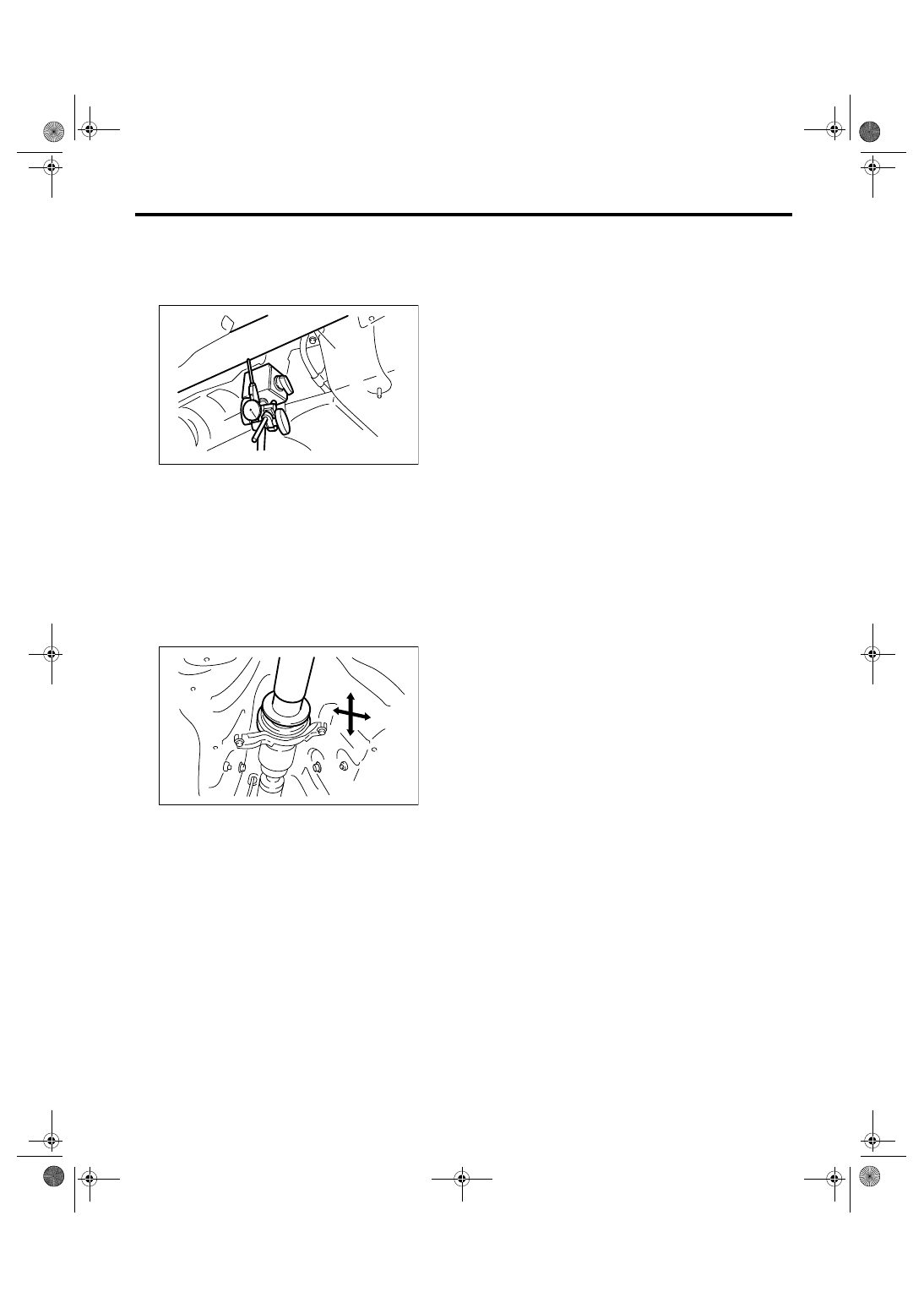
4) Move the propeller shaft near center bearing up
and down, and left and right with your hand to
check for any abnormal bearing free play.
(A) Propeller shaft
(B) Dial gauge
DS-00036
(B)
(A)
DS-00037
DS-13
DRIVE SHAFT SYSTEM
Front Axle
3. Front Axle
A: REMOVAL
1) Disconnect the ground cable from battery.
2) Lift-up the vehicle and remove the front wheels.
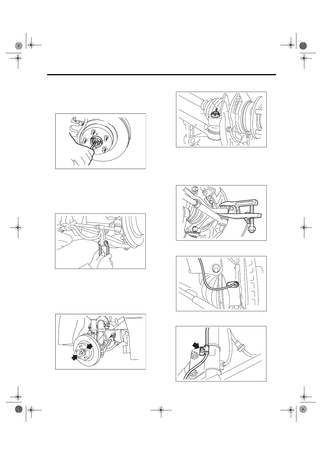
3) Unlock the axle nut.
4) Remove the axle nut using a socket wrench
while depressing the brake pedal.
CAUTION:
Remove the wheel before loosening the axle
nut. Failure to follow this rule may damage the
wheel bearings.
5) Remove the stabilizer link.
6) Remove the disc brake caliper from housing,
and suspend it from strut using a wire.
7) Remove the disc rotor from hub.
NOTE:
If the disc rotor seizes up within hub, drive disc rotor
out by installing an 8-mm bolt in screw hole on ro-
tor.
8) Remove the cotter pin and castle nut which se-
cure tie-rod end to housing knuckle arm.
9) Using a puller, remove the tie-rod ball joint from
knuckle arm.
10) Remove the ABS wheel speed sensor assem-
bly and harness.
11) Remove the bolts which secure sensor harness
to strut.
DS-00038
DS-00143
DS-00041
(A) Cotter pin
(B) Castle nut
(C) Tie-rod
DS-00042
(C)
(B)
(A)
DS-00043
DS-00249
DS-00144
S301.fm 13 ページ 2007年12月3日 月曜日 午後1時45分
DS-14
DRIVE SHAFT SYSTEM
Front Axle
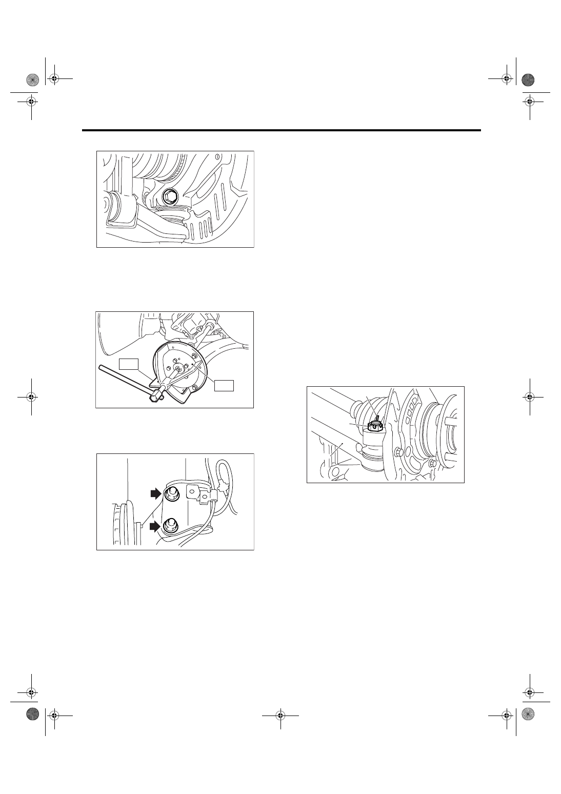
12) Remove the front arm ball joint from housing.
13) Remove the PTJ from transmission.
14) Remove the front drive shaft assembly from
hub. If it is hard to remove, use STs.
ST1
926470000
AXLE SHAFT PULLER
ST2
927140000
AXLE SHAFT PULLER
PLATE
15) After scribing an alignment mark on camber ad-
justing bolt head, remove the bolts which connect
housing and strut, and disconnect the housing from
strut.
B: INSTALLATION
1) While aligning the alignment mark on the cam-
ber adjusting bolt head, tighten the housing and
strut using a new self-locking nut.
Tightening torque:
175 N
⋅
m (17.8 kgf-m, 129 ft-lb)
2) Install the front drive shaft. <Ref. to DS-22, IN-
STALLATION, Front Drive Shaft.>
3) Install the front arm ball joint to housing.
Tightening torque:
50 N
⋅
m (5.1 kgf-m, 36.9 ft-lb)
4) Install the ABS wheel speed sensor harness to
strut.
5) Install the ABS wheel speed sensor on housing.
Tightening torque:
32 N
⋅
m (3.3 kgf-m, 23.9 ft-lb)
6) Install the disc rotor on hub.
7) Install the disc brake caliper on housing.
Tightening torque:
80 N
⋅
m (8.2 kgf-m, 59 ft-lb)
8) Install the stabilizer link.
9) Connect the tie-rod end ball joint to the knuckle
arm with a castle nut.
Tightening torque:
27.0 N
⋅
m (2.75 kgf-m, 19.9 ft-lb)
CAUTION:
When connecting, do not hit the cap at bottom
of tie-rod end with hammer.
10) Tighten the castle nut to specified torque and
tighten further within 60
° until the pin hole is aligned
with the slot in nut. Bend the cotter pin to lock.
11) While depressing the brake pedal, tighten a
new axle nut (olive color) to specified torque and
lock it securely.
Tightening torque:
220 N
⋅
m (22.4 kgf-m, 162 ft-lb)
CAUTION:
• Install the wheel after installation of axle nut.
Failure to follow this rule may damage the
wheel bearing.
• Be sure to tighten the axle nut to specified
torque. Do not overtighten it as this may dam-
age wheel bearing.
DS-00045
DS-00145
ST2
ST1
DS-00046
(A) Cotter pin
(B) Castle nut
(C) Tie-rod
DS-00042
(C)
(B)
(A)
Нет комментариевНе стесняйтесь поделиться с нами вашим ценным мнением.
Текст