Subaru Legacy (2005 year). Service manual — part 326
EN(H4DOTC)(diag)-73
ENGINE (DIAGNOSTICS)
Diagnostic Procedure with Diagnostic Trouble Code (DTC)
5
CHECK REAR OXYGEN SENSOR.
1) Turn the ignition switch to OFF.
2) Measure the resistance between rear oxy-
gen sensor connector terminals.
Terminals
No. 1 — No. 2:
Is the resistance less than 30
Ω?
Repair the har-
ness and connec-
tor.
NOTE:
In this case, repair
the following:
• Open circuit of
harness between
rear oxygen sen-
sor and ECM con-
nector
• Poor contact in
rear oxygen sen-
sor connector
• Poor contact in
ECM connector
• Poor contact in
coupling connector
Replace the rear
oxygen sensor.
<Ref. to
FU(H4DOTC)-33,
Rear Oxygen Sen-
sor.>
Step
Check
Yes
No
EN(H4DOTC)(diag)-74
ENGINE (DIAGNOSTICS)
Diagnostic Procedure with Diagnostic Trouble Code (DTC)
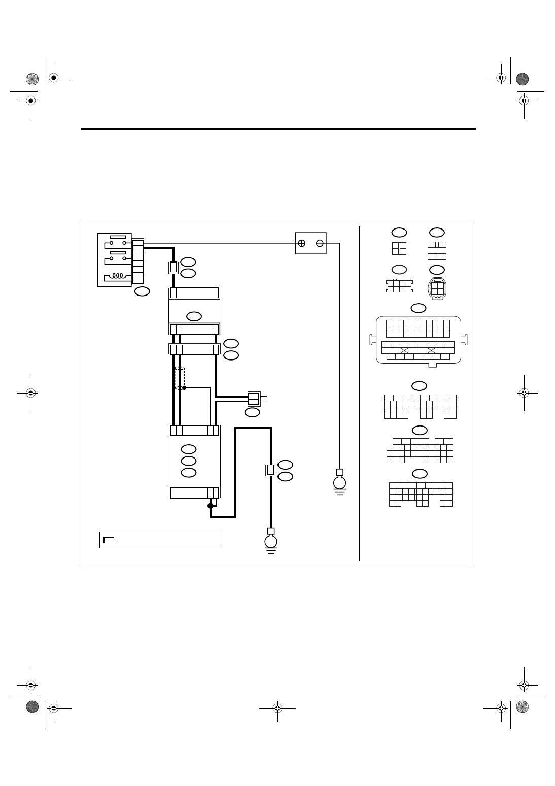
D: DTC P0038 HO2S HEATER CONTROL CIRCUIT HIGH (BANK 1 SENSOR 2)
DTC DETECTING CONDITION:
Detects when malfunction occurs in 2 continuous driving cycles.
CAUTION:
After repair or replacement of faulty parts, perform Clear Memory Mode <Ref. to EN(H4DOTC)(diag)-
37, OPERATION, Clear Memory Mode.> and Inspection Mode <Ref. to EN(H4DOTC)(diag)-30, PROCE-
DURE, Inspection Mode.>.
WIRING DIAGRAM:
EN-03555
1 2 3 4
5 6 7 8
B83
BATTERY
MAIN RELAY
B47
1
2
4
6
3
5
E
E
B21
E2
35
*
*
B83
3
4
1
2
5
6
B135
B47
B19
B136
1
4
2
3
T6
REAR
OXYGEN SENSOR
B4
B1
B2
D25
D31
C35
ECM
B136
B137
C:
B135
B:
D:
1
2
3
4
B:
C:
B137
D:
5
6
7 8
2
1
9
4
3
10
24
22 23
25
11 12 13 14 15
26 27
28
16
17 18 19 20 21
33 34
29
32
30
31
35
5
6
7
8
2
1
9
4
3
10
24
22 23
25
11 12 13 14 15
26 27
28
16 17 18 19
20 21
29 30 31
32 33
34 35
5
6
7
8
2
1
9
4
3
10
22 23
11 12 13 14 15
24 25
26
16 17
18 19 20 21
27
28 29
30 31
B19
T5
2
T5
B19
3
1
4
B21
1 2 3 4
12 13 14 15
5 6 7 8
16 17 18 19
9 10 11
20 21 22
23 24 25 26 27 28 29 30 31 32 33
35
34
37
36
39
38
41
40
43
42
44
45
47
46
49
48
51
50
53
52
54
T6
2 1
4 3
*
: TERMINAL No. RANDOM ARRANGEMENT

EN(H4DOTC)(diag)-75
ENGINE (DIAGNOSTICS)
Diagnostic Procedure with Diagnostic Trouble Code (DTC)
Step
Check
Yes
No
1
CHECK GROUND CIRCUIT FOR ECM.
1) Turn the ignition switch to OFF.
2) Disconnect the connector from ECM.
3) Measure the resistance of harness
between ECM connector and chassis ground.
Connector & terminal
(B135) No. 4 — Chassis ground:
(B135) No. 1 — Chassis ground:
Is the resistance less than 5
Ω?
Repair the har-
ness and connec-
tor.
NOTE:
In this case, repair
the following:
• Open circuit of
harness between
ECM and engine
ground cable
• Poor contact in
ECM connector
• Poor contact in
coupling connector
2
CHECK HARNESS BETWEEN ECM AND
REAR OXYGEN SENSOR.
Measure the voltage between ECM and chas-
sis ground.
Connector & terminal
(B135) No. 2 (+) — Chassis ground (
−
):
Is the voltage more than 10 V? Repair the battery
short circuit of har-
ness between
ECM and rear oxy-
gen sensor.
Repair the poor
connection in ECM
connector.
EN(H4DOTC)(diag)-76
ENGINE (DIAGNOSTICS)
Diagnostic Procedure with Diagnostic Trouble Code (DTC)
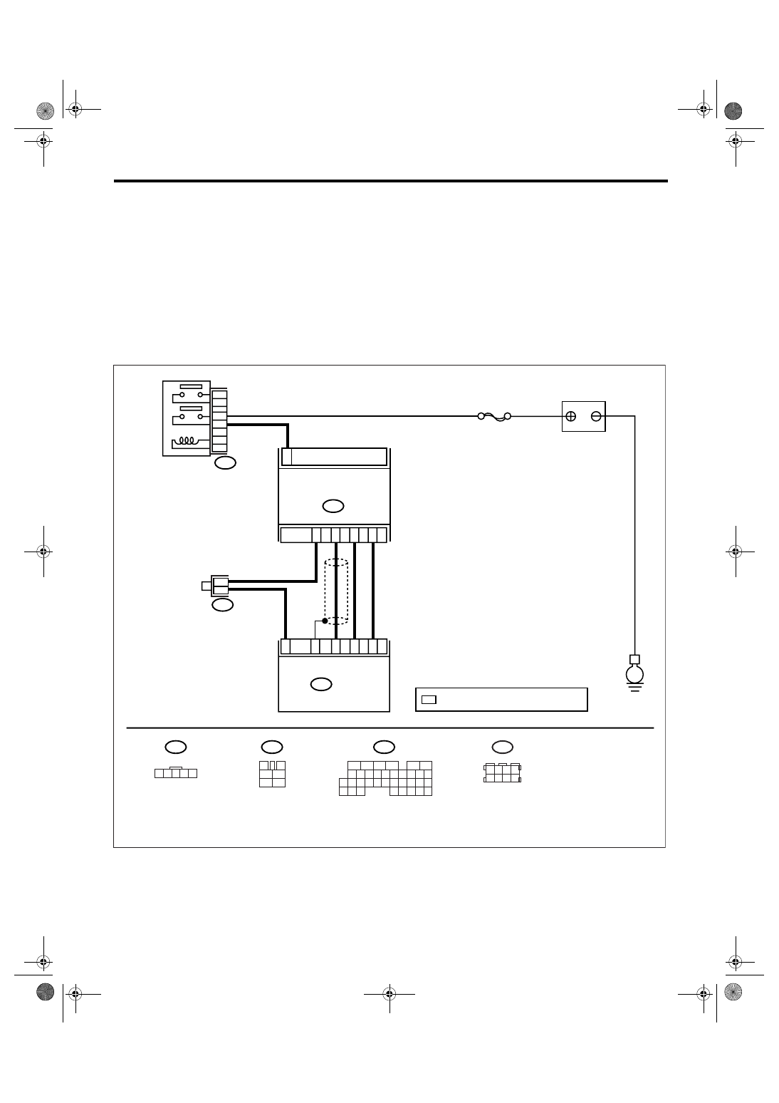
E: DTC P0102 MASS OR VOLUME AIR FLOW CIRCUIT LOW INPUT
DTC DETECTING CONDITION:
Immediately at fault recognition
TROUBLE SYMPTOM:
• Erroneous idling
• Engine stalls.
• Poor driving performance
CAUTION:
After repair or replacement of faulty parts, perform Clear Memory Mode <Ref. to EN(H4DOTC)(diag)-
37, OPERATION, Clear Memory Mode.> and Inspection Mode <Ref. to EN(H4DOTC)(diag)-30, PROCE-
DURE, Inspection Mode.>.
WIRING DIAGRAM:
EN-03523
B3
E
B83
1
B3
ECM
B136
SBF-7
1 2 3 4 5
3
4
1
2
5
6
B136
B47
*
*
2
4
3
5
31
13
23
35
32
B47
1
2
4
6
3
5
1 2 3 4
5 6 7 8
B83
5
6
7 8
2
1
9
4
3
10
24
22 23
25
11 12 13 14 15
26 27
28
16
17 18 19 20 21
33 34
29
32
30
31
35
BATTERY
MASS AIR FLOW AND
INTAKE AIR TEMPERATURE
SENSOR
MAIN RELAY
*
: TERMINAL No. RANDOM ARRANGEMENT
Нет комментариевНе стесняйтесь поделиться с нами вашим ценным мнением.
Текст