Subaru Legacy (2005 year). Service manual — part 324

EN(H4DOTC)(diag)-65
ENGINE (DIAGNOSTICS)
List of Diagnostic Trouble Code (DTC)
P1577
IMM Control Module EEPROM
P1578
Meter Failure
P2088
Intake Camshaft Position Actuator
Control Circuit Low (Bank 1)
P2089
Intake Camshaft Position Actuator
Control Circuit High (Bank 1)
P2090
Exhaust Camshaft Position Actua-
tor Control Circuit Low (Bank 1)
P2091
Exhaust Camshaft Position Actua-
tor Control Circuit High (Bank 1)
P2092
Intake Camshaft Position Actuator
Control Circuit Low (Bank 2)
P2093
Intake Camshaft Position Actuator
Control Circuit High (Bank 2)
P2094
Exhaust Camshaft Position Actua-
tor Control Circuit Low (Bank 2)
P2095
Exhaust Camshaft Position Actua-
tor Control Circuit High (Bank 2)
P2101
Throttle Actuator Control Motor Cir-
cuit Range/Performance
P2102
Throttle Actuator Control Motor Cir-
cuit Low
P2103
Throttle Actuator Control Motor Cir-
cuit High
P2109
Throttle/Pedal Position Sensor “A”
Minimum Stop Performance
P2122
Throttle/Pedal Position Sensor/
Switch “D” Circuit Low Input
P2123
Throttle/Pedal Position Sensor/
Switch “D” Circuit High Input
P2127
Throttle/Pedal Position Sensor/
Switch “E” Circuit Low Input
P2128
Throttle/Pedal Position Sensor/
Switch “E” Circuit High Input
P2135
Throttle/Pedal Position Sensor/
Switch “A”/“B” Voltage Correlation
DTC
Item
Reference

EN(H4DOTC)(diag)-66
ENGINE (DIAGNOSTICS)
List of Diagnostic Trouble Code (DTC)
P2138
Throttle/Pedal Position Sensor/
Switch “D”/“E” Voltage Correlation
P2228
Barometric Pressure Circuit Low
P2229
Barometric Pressure Circuit High
DTC
Item
Reference
EN(H4DOTC)(diag)-67
ENGINE (DIAGNOSTICS)
Diagnostic Procedure with Diagnostic Trouble Code (DTC)
18.Diagnostic Procedure with Diagnostic Trouble Code (DTC)
A: DTC P0031 HO2S HEATER CONTROL CIRCUIT LOW (BANK 1 SENSOR 1)
DTC DETECTING CONDITION:
Immediately at fault recognition
CAUTION:
After repair or replacement of faulty parts, perform Clear Memory Mode <Ref. to EN(H4DOTC)(diag)-
37, OPERATION, Clear Memory Mode.> and Inspection Mode <Ref. to EN(H4DOTC)(diag)-30, PROCE-
DURE, Inspection Mode.>.
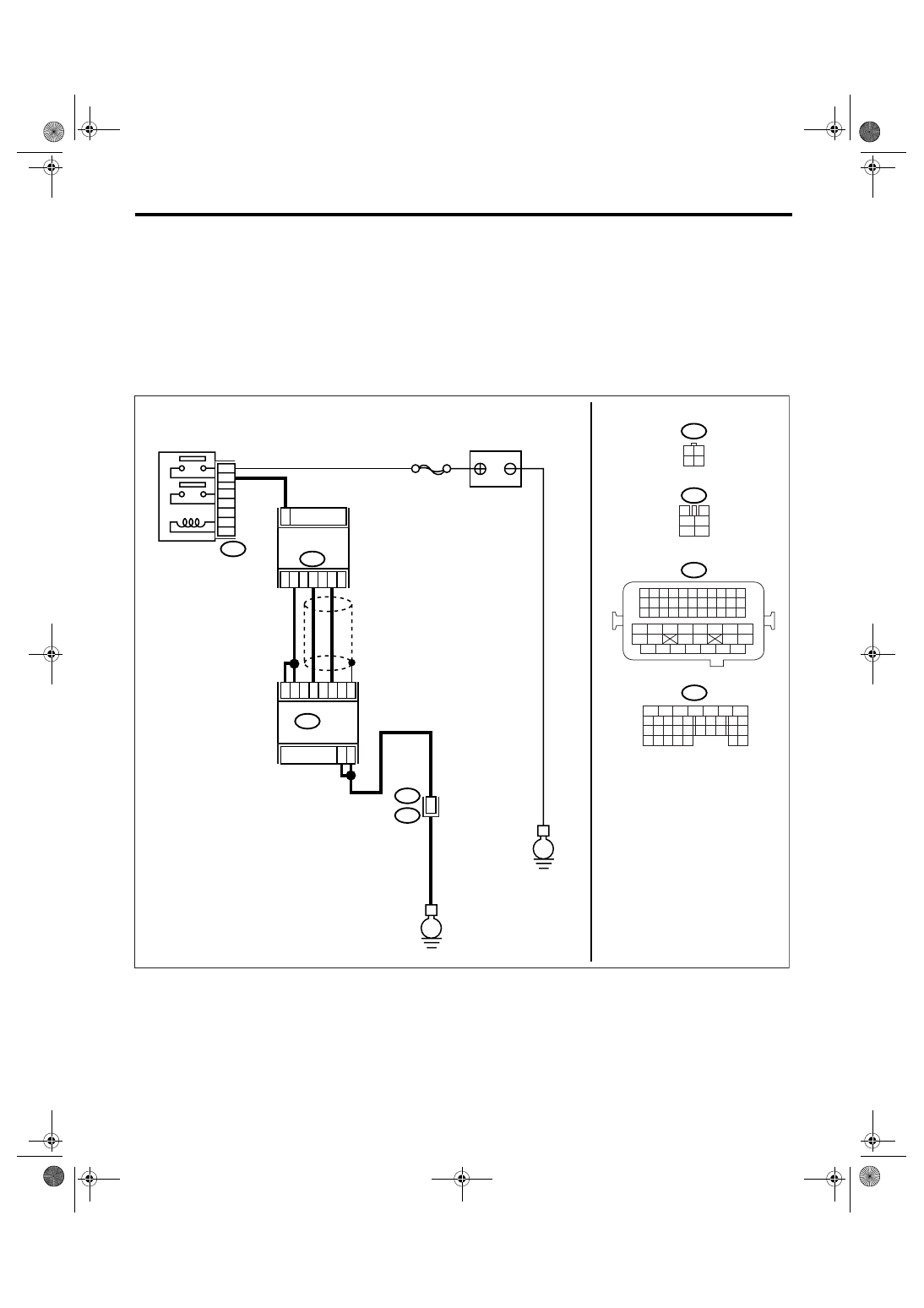
WIRING DIAGRAM:
EN-03522
SBF-5
B47
1
2
4
6
3
5
E
E
B21
F2
54
A6
A7
A2
A3
A26
A33
A25
ECM
B134
3
1
4
2
B18
3 4
1 2
3
4
1
2
5
6
B21
B47
B18
B134
5
6
7
8
2
1
9
4
3
10
24
22 23
25
11 12 13 14 15
26 27
28
16 17
18 19 20 21
33 34
29
32
30 31
MAIN RELAY
FRONT OXYGEN
(A/F) SENSOR
BATTERY
A:
1 2 3 4
12 13 14 15
5 6 7 8
16 17 18 19
9 10 11
20 21 22
23 24 25 26 27 28 29 30 31 32 33
35
34
37
36
39
38
41
40
43
42
44
45
47
46
49
48
51
50
53
52
54
A:

EN(H4DOTC)(diag)-68
ENGINE (DIAGNOSTICS)
Diagnostic Procedure with Diagnostic Trouble Code (DTC)
Step
Check
Yes
No
1
CHECK POWER SUPPLY TO FRONT OXY-
GEN (A/F) SENSOR.
1) Turn the ignition switch to OFF.
2) Disconnect the connector from front oxygen
(A/F) sensor.
3) Turn the ignition switch to ON.
4) Measure the voltage between front oxygen
(A/F) sensor connector and engine ground.
Connector & terminal
(B18) No. 3 (+) — Engine ground (
−
):
Is the voltage more than 10 V? Go to step 2.
Repair the power
supply line.
NOTE:
In this case, repair
the following:
• Open circuit of
harness between
main relay and
front oxygen (A/F)
sensor connector
• Poor contact in
front oxygen (A/F)
sensor connector
• Poor contact in
main relay connec-
tor
2
CHECK HARNESS BETWEEN FRONT OXY-
GEN (A/F) SENSOR AND ECM.
1) Turn the ignition switch to OFF.
2) Disconnect the connector from ECM.
3) Measure the resistance between front oxy-
gen (A/F) sensor connector and ECM connec-
tor.
Connector & terminal
(B18) No. 4 — (B134) No. 2:
(B18) No. 4 — (B134) No. 3:
Is the resistance less than 1
Ω?
Repair the open
circuit of harness
between ECM and
front oxygen (A/F)
sensor.
3
CHECK HARNESS BETWEEN FRONT OXY-
GEN (A/F) SENSOR AND ECM.
Measure the resistance between ECM connec-
tor and chassis ground.
Connector & terminal
(B134) No. 2 — Chassis ground:
(B134) No. 3 — Chassis ground:
Is the resistance more than 1
M
Ω?
Repair the ground
short circuit of har-
ness between
ECM and front
oxygen (A/F) sen-
sor.
4
CHECK FRONT OXYGEN (A/F) SENSOR.
1) Turn the ignition switch to OFF.
2) Measure the resistance between front oxy-
gen (A/F) sensor connector terminals.
Terminals
No. 3 — No. 4:
Is the resistance 2.4
Ω?
Repair the poor
contact in ECM
connector.
Replace the front
oxygen (A/F) sen-
sor. <Ref. to
FU(H4DOTC)-32,
Front Oxygen (A/
F) Sensor.>
Нет комментариевНе стесняйтесь поделиться с нами вашим ценным мнением.
Текст