Subaru Legacy (2005 year). Service manual — part 115

EN(H4SO 2.0)(diag)-49
ENGINE (DIAGNOSTICS)
Malfunction Indicator Light
2
CHECK HARNESS BETWEEN ECM CON-
NECTOR AND CHASSIS GROUND TERMI-
NAL.
1) Turn the ignition switch to OFF.
2) Disconnect the connector from ECM.
3) Measure the resistance of harness
between ECM connector and chassis ground.
Connector & terminal
(B135) No. 24 — Chassis ground:
Is the resistance less than 5
Ω?
Repair the short
circuit of harness
between ECM and
test mode connec-
tor.
Replace the ECM.
<Ref. to FU(H4SO
2.0)-34, Engine
Control Module
(ECM).>
Step
Check
Yes
No
EN(H4SO 2.0)(diag)-50
ENGINE (DIAGNOSTICS)
Diagnostics for Engine Starting Failure
16.Diagnostics for Engine Starting Failure
A: PROCEDURE
1. Check for fuel amount.
↓
2. Inspection of starter motor circuit. <Ref. to EN(H4SO 2.0)(diag)-51, STARTER MOTOR CIRCUIT, Diagnostics for Engine Start-
ing Failure.>
↓
3. Inspection of ECM power supply and ground line. <Ref. to EN(H4SO 2.0)(diag)-54, CHECK POWER SUPPLY AND GROUND
LINE OF ENGINE CONTROL MODULE (ECM), Diagnostics for Engine Starting Failure.>
↓
4. Inspection of ignition control system. <Ref. to EN(H4SO 2.0)(diag)-56, IGNITION CONTROL SYSTEM, Diagnostics for Engine
Starting Failure.>
↓
5. Inspection of fuel pump circuit. <Ref. to EN(H4SO 2.0)(diag)-59, FUEL PUMP CIRCUIT, Diagnostics for Engine Starting Fail-
ure.>
↓
6. Inspection of fuel injector circuit. <Ref. to EN(H4SO 2.0)(diag)-62, FUEL INJECTOR CIRCUIT, Diagnostics for Engine Starting
Failure.>
EN(H4SO 2.0)(diag)-51
ENGINE (DIAGNOSTICS)
Diagnostics for Engine Starting Failure
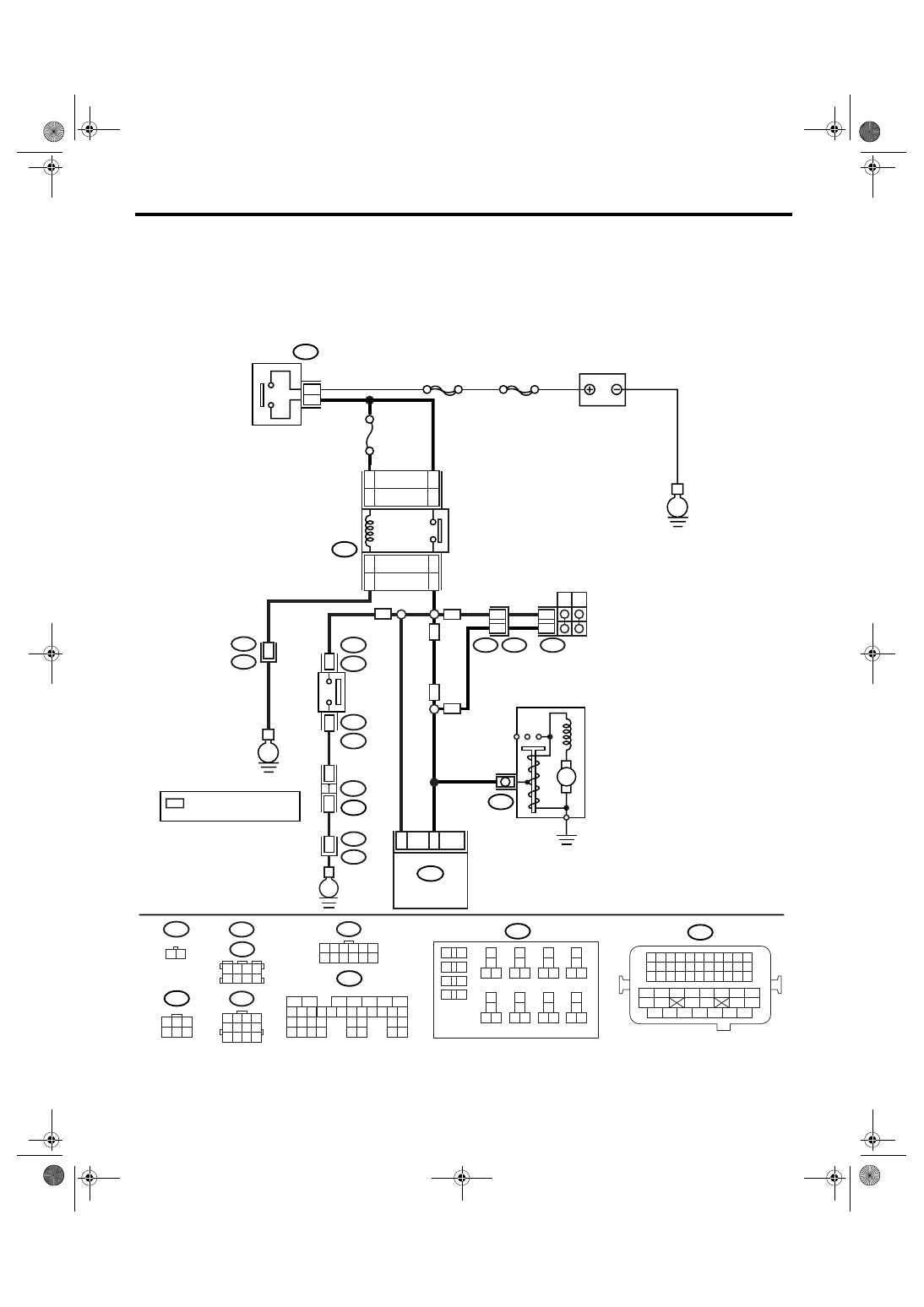
B: STARTER MOTOR CIRCUIT
CAUTION:
After repair or replacement of faulty parts, perform Clear Memory Mode <Ref. to EN(H4SO 2.0)(diag)-
38, OPERATION, Clear Memory Mode.> and Inspection Mode <Ref. to EN(H4SO 2.0)(diag)-32, PRO-
CEDURE, Inspection Mode.>.
WIRING DIAGRAM:
EN-03471
B225
10
11 12
13
14
15 16
17
18
19 20
21
22
23 24
25
26
27 28
29
30
31 32
33
34
35 36
39 40
37
38
1
2
9
3
4
5
6
7
8
B12
1 2 3 4
5 6 7 8
9 10 11 12
B25
1 2
1 2 3 4
5 6 7 8
B83
B122
T7
1 2 3 4 5 6
7 8 9 10 11 12
B135
1
2
7
8 9
5
6
3
4
10 11 12
19
20 21
29 30 31
13 14 15 16 17
27
28
18
22 23
24 25
26
32 33
34 35
B21
1 2 3 4
12 13 14 15
5 6 7 8
16 17 18 19
9 10 11
20 21 22
23 24 25 26 27 28 29 30 31 32 33
35
34
37
36
39
38
41
40
43
42
44
45
47
46
49
48
51
50
53
52
54
B72
1
3
4 5 6
2
23
ECM
B135
B14
M
STARTER MOTOR
E
12
12
B12
T3
T7
P
N
7
11
AT
AT
MT
MT
No.21
MAIN SBF
SBF-6
E
B72
2
3
BATTERY
IGNITION
SWITCH
B225
16
14
16
14
STARTER
RELAY
15
13
15
13
LHD
RHD
LHD
RHD
MT
12
B21
E2
E
36
NEUTRAL
POSITION
SWITCH
1
B25
T2
T2
B25
2
*
B83
B122 : LHD
: RHD
JOINT
CONNECTOR
*
B21
E2
35
*
: TERMINAL No. RANDOM
ARRANGEMENT
EN(H4SO 2.0)(diag)-52
ENGINE (DIAGNOSTICS)
Diagnostics for Engine Starting Failure
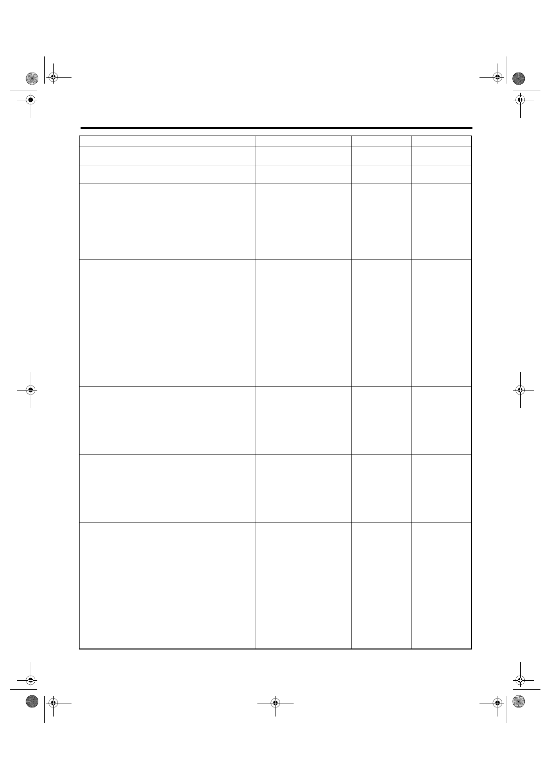
Step
Check
Yes
No
1
CHECK BATTERY.
Check the battery voltage.
Is the voltage more than 12 V? Go to step 2.
Charge or replace
the battery.
2
CHECK OPERATION OF STARTER MOTOR. Does the starter motor oper-
ate?
3
CHECK DTC.
Is DTC displayed? <Ref. to
EN(H4SO 2.0)(diag)-31,
OPERATION, Read Diagnos-
tic Trouble Code (DTC).>
Inspect the rele-
vant DTC using
List of Diagnostic
Trouble Code
(DTC). <Ref. to
EN(H4SO
2.0)(diag)-64, List
of Diagnostic Trou-
ble Code (DTC).>
Repair the poor
contact in ECM
connector.
4
CHECK INPUT SIGNAL OF STARTER MO-
TOR.
1) Turn the ignition switch to OFF.
2) Disconnect the connector from starter
motor.
3) Turn the ignition switch to START.
4) Measure the power supply voltage between
starter motor connector terminal and engine
ground.
Connector & terminal
(B14) No. 1 (+) — Engine ground (
−
):
NOTE:
• For AT model, place the select lever in “P” or
“N” range.
• For MT model, depress the clutch pedal.
Is the voltage more than 10 V? Check the starter
motor. <Ref. to
SC(H4SO 2.0)-6,
Starter.>
5
CHECK HARNESS BETWEEN BATTERY
AND IGNITION SWITCH CONNECTOR.
1) Disconnect the connector from ignition
switch.
2) Measure the power supply voltage between
ignition switch connector and chassis ground.
Connector & terminal
(B72) No. 3 (+) — Chassis ground (
−
):
Is the voltage more than 10 V? Go to step 6.
Repair the open
circuit of harness
between ignition
switch and bat-
tery, and check
fuse SBF No. 6
and MAIN SBF.
6
CHECK IGNITION SWITCH.
1) Disconnect the connector from ignition
switch.
2) Measure the resistance between ignition
switch terminals after turning the ignition
switch to START position.
Terminals
No. 2 — No. 3:
Is the resistance less than 5
Ω?
Replace the igni-
tion switch.
7
CHECK INPUT VOLTAGE OF STARTER RE-
LAY.
1) Turn the ignition switch to OFF.
2) Disconnect the connector from starter relay.
3) Connect the connector to ignition switch.
4) Measure the input voltage between starter
relay connector and chassis ground after turn-
ing the ignition switch to START position.
Connector & terminal
LHD model
(B225) No. 13 (+) — Chassis ground (
−
):
(B225) No. 15 (+) — Chassis ground (
−
):
RHD model
(B225) No. 14 (+) — Chassis ground (
−
):
(B225) No. 16 (+) — Chassis ground (
−
):
Is the voltage more than 10 V? Go to step 8.
Repair the open
circuit of harness
between starter
relay and ignition
switch.
Нет комментариевНе стесняйтесь поделиться с нами вашим ценным мнением.
Текст