Subaru Legacy (2005 year). Service manual — part 116
EN(H4SO 2.0)(diag)-53
ENGINE (DIAGNOSTICS)
Diagnostics for Engine Starting Failure
8
CHECK STARTER RELAY.
1) Connect the battery to starter relay termi-
nals No. 15 and No. 16.
2) Measure the resistance between starter
relay terminals.
Terminals
No. 13 — No. 14:
Is the resistance less than 1
Ω?
Replace the
starter relay.
9
CHECK INPUT VOLTAGE OF ECM.
1) Turn the ignition switch to OFF.
2) Connect the connector to starter relay.
3) Disconnect the connector from ECM.
4) Turn the ignition switch to START.
5) Measure the voltage between ECM and
chassis ground.
Connector & terminal
(B135) No. 23 (+) — Chassis ground (
−
):
Is the voltage more than 10 V? Replace the ECM.
<Ref. to FU(H4SO
2.0)-34, Engine
Control Module
(ECM).>
Repair the open or
ground short cir-
cuit of harness
between ECM and
starter relay.
For AT model,
check the inhibitor
switch. <Ref. to
4AT-51, INSPEC-
TION, Inhibitor
Switch.>
Step
Check
Yes
No
EN(H4SO 2.0)(diag)-54
ENGINE (DIAGNOSTICS)
Diagnostics for Engine Starting Failure
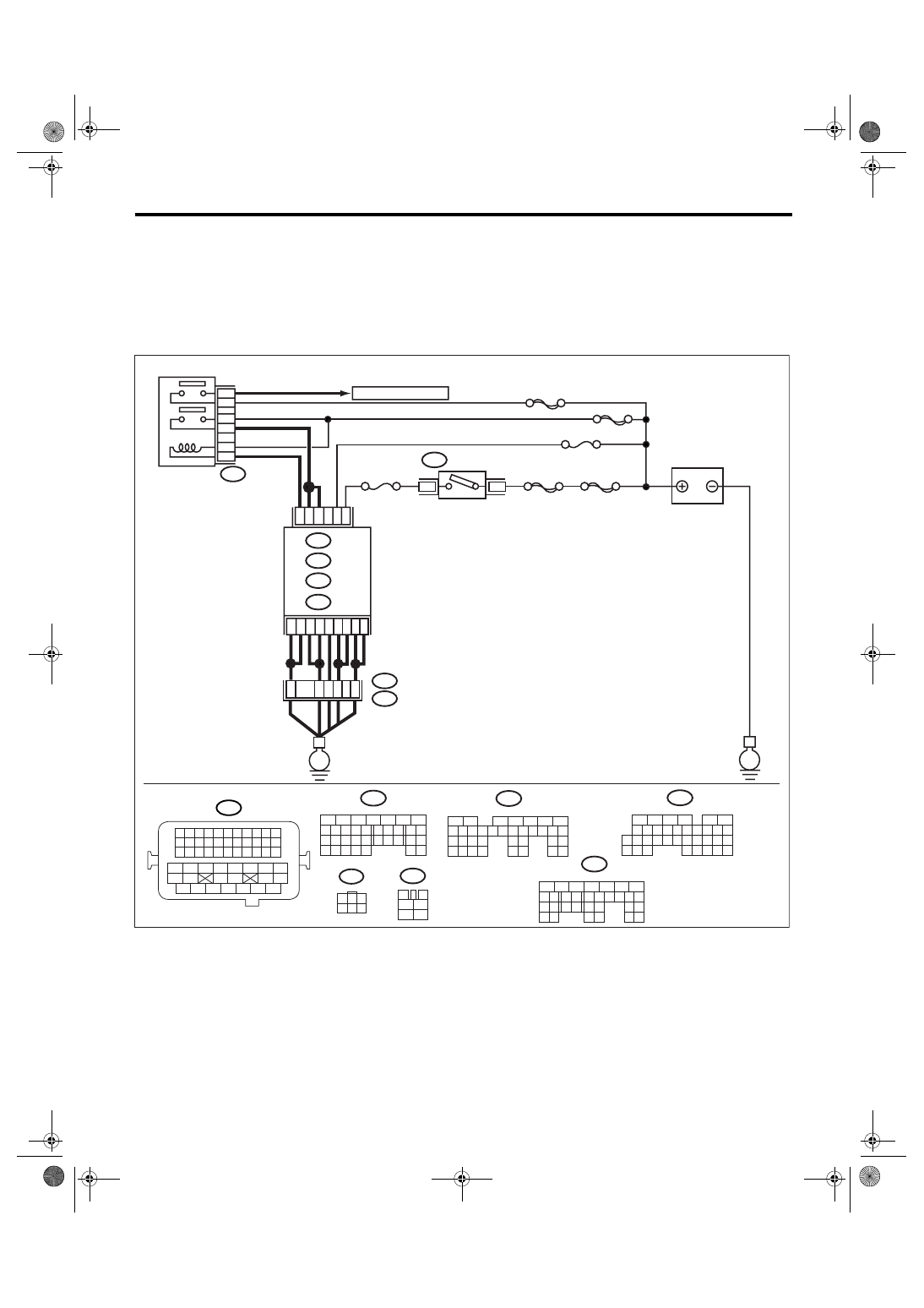
C: CHECK POWER SUPPLY AND GROUND LINE OF ENGINE CONTROL MOD-
ULE (ECM)
CAUTION:
After repair or replacement of faulty parts, perform Clear Memory Mode <Ref. to EN(H4SO 2.0)(diag)-
38, OPERATION, Clear Memory Mode.> and Inspection Mode <Ref. to EN(H4SO 2.0)(diag)-32, PRO-
CEDURE, Inspection Mode.>.
WIRING DIAGRAM:
EN-03507
BATTERY
IGNITION
SWITCH
MAIN RELAY
SBF-6
MAIN SBF
SBF-7
B72
C4
C3
B14
B5
C6
B6
C1
C2
A7
C5
C7
B13
No.12
B47
E2
B21
2
1
4
6
5
3
ECM
E
E
3
6
B134
B135
A:
D: B137
B:
D1
52
37
36
34
3
4
1
2
5
6
B47
No.13
A2
35
B134
5
6
7
8
2
1
9
4
3
10
24
22 23
25
11 12 13 14 15
26 27
28
16 17
18 19 20 21
33 34
29
32
30 31
B135
5
6
7
8
2
1
9
4
3
10
24
22 23
25
11 12 13 14 15
26 27
28
16 17 18 19
20 21
29 30 31
32 33
34 35
B137
5
6
7
8
2
1
9
4
3
10
22 23
11 12 13 14 15
24 25
26
16 17
18 19 20 21
27
28 29
30 31
B21
1 2 3 4
12 13 14 15
5 6 7 8
16 17 18 19
9 10 11
20 21 22
23 24 25 26 27 28 29 30 31 32 33
35
34
37
36
39
38
41
40
43
42
44
45
47
46
49
48
51
50
53
52
54
B72
1
3
4 5 6
2
A:
B:
D:
B136
C:
B136
5
6
7 8
2
1
9
4
3
10
24
22 23
25
11 12 13 14 15
26 27
28
16
17 18 19 20 21
33 34
29
32
30
31
35
C:
SBF-5
TO OXYGEN SENSOR
EN(H4SO 2.0)(diag)-55
ENGINE (DIAGNOSTICS)
Diagnostics for Engine Starting Failure
Step
Check
Yes
No
1
CHECK MAIN RELAY.
1) Turn the ignition switch to OFF.
2) Remove the main relay.
3) Connect the battery to main relay terminals
No. 1 and No. 2.
4) Measure the resistance between main relay
terminals.
Terminals
No. 3 — No. 5:
No. 4 — No. 6:
Is the resistance less than 10
Ω?
Replace the main
relay.
2
CHECK GROUND CIRCUIT FOR ECM.
1) Disconnect the connector from ECM.
2) Measure the resistance of harness
between ECM and chassis ground.
Connector & terminal
(B134) No. 2 — Chassis ground:
(B134) No. 7 — Chassis ground:
(B135) No. 5 — Chassis ground:
(B135) No. 6 — Chassis ground:
(B136) No. 1 — Chassis ground:
(B136) No. 2 — Chassis ground:
(B136) No. 5 — Chassis ground:
(B136) No. 6 — Chassis ground:
(B137) No. 1 — Chassis ground:
Is the resistance less than 5
Ω?
Repair the open
circuit of harness
between ECM
connector and
engine grounding
terminal.
3
CHECK INPUT VOLTAGE OF ECM.
Measure the voltage between ECM connector
and chassis ground.
Connector & terminal
(B136) No. 7 (+) — Chassis ground (
−
):
Is the voltage more than 10 V? Go to step 4.
Repair the open or
ground short cir-
cuit of power sup-
ply circuit.
4
CHECK INPUT VOLTAGE OF ECM.
1) Turn the ignition switch to ON.
2) Measure the voltage between ECM con-
nector and chassis ground.
Connector & terminal
(B135) No. 13 (+) — Chassis ground (
−
):
Is the voltage more than 10 V? Go to step 5.
Repair the open or
ground short cir-
cuit of power sup-
ply circuit.
5
CHECK INPUT VOLTAGE OF MAIN RELAY.
Measure the voltage between main relay con-
nector and chassis ground.
Connector & terminal
(B47) No. 1 (+) — Chassis ground (
−
):
Is the voltage more than 10 V? Go to step 6.
Repair the open
circuit of harness
between ECM
connector and
main relay connec-
tor.
6
CHECK INPUT VOLTAGE OF ECM.
1) Connect the connectors to ECM and main
relay.
2) Turn the ignition switch to ON.
3) Measure the voltage between ECM con-
nector and chassis ground.
Connector & terminal
(B135) No. 14 (+) — Chassis ground (
−
):
Is the voltage more than 10 V? Go to step 7.
Repair the open or
ground short cir-
cuit of harness
between ECM
connector and
main relay connec-
tor.
7
CHECK INPUT VOLTAGE OF MAIN RELAY.
Measure the voltage between main relay con-
nector and chassis ground.
Connector & terminal
(B47) No. 5 (+) — Chassis ground (
−
):
(B47) No. 6 (+) — Chassis ground (
−
):
Is the voltage more than 10 V? Go to step 8.
Repair the open or
ground short cir-
cuit of harness of
power supply cir-
cuit.
EN(H4SO 2.0)(diag)-56
ENGINE (DIAGNOSTICS)
Diagnostics for Engine Starting Failure
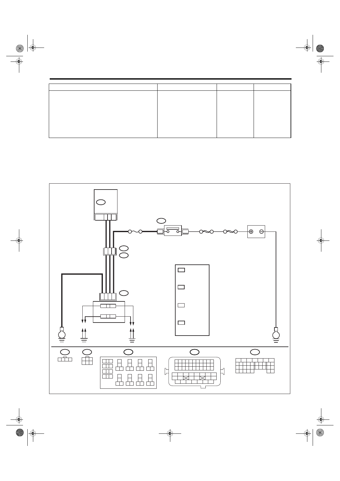
D: IGNITION CONTROL SYSTEM
CAUTION:
After repair or replacement of faulty parts, perform Clear Memory Mode <Ref. to EN(H4SO 2.0)(diag)-
38, OPERATION, Clear Memory Mode.> and Inspection Mode <Ref. to EN(H4SO 2.0)(diag)-32, PRO-
CEDURE, Inspection Mode.>.
WIRING DIAGRAM:
8
CHECK INPUT VOLTAGE OF ECM.
1) Turn the ignition switch to ON.
2) Measure the voltage between ECM con-
nector and chassis ground.
Connector & terminal
(B136) No. 3 (+) — Chassis ground (
−
):
(B136) No. 4 (+) — Chassis ground (
−
):
Is the voltage more than 10 V? Check ignition
control system.
<Ref. to EN(H4SO
2.0)(diag)-56,
IGNITION CON-
TROL SYSTEM,
Diagnostics for
Engine Starting
Failure.>
Repair the open or
ground short cir-
cuit of harness
between ECM
connector and
main relay connec-
tor.
Step
Check
Yes
No
EN-03472
BATTERY
3
IGNITION
SWITCH
6
24
B21
E2
E12
MAIN SBF
13
49
15
B134
ECM
23
3
4
1
2
IGNITION COIL
&
IGNITOR ASSY
B72
E
E
B21
1 2 3 4
12 13 14 15
5 6 7 8
16 17 18 19
9 10 11
20 21 22
23 24 25 26 27 28 29 30 31 32 33
35
34
37
36
39
38
41
40
43
42
44
45
47
46
49
48
51
50
53
52
54
B72
E12
9
10
1
2
3
4
5
6
7
8
11 12
14
15 16
13
18
19 20
17
22
23 24
21
38
39 40
37
34
35 36
33
30
31 32
29
26
27 28
25
B225
SBF-6
No.12
1 2 3 4
1
3
4 5 6
2
B134
5
6
7
8
2
1
9
4
3
10
24
22 23
25
11 12 13 14 15
26 27
28
16 17
18 19 20 21
33 34
29
32
30 31
2.0 L : 1
2.5 L LHD : 2
2.5 L RHD : 4
2.0 L : 4
2.5 L LHD : 1
2.5 L RHD : 1
2.0 L : 2
2.5 L LHD : 4
2.5 L RHD : 3
2.0 L : 3
2.5 L LHD : 3
2.5 L RHD : 2
*
1
*
*
2
3
*
4
3
4
2
*
1
*
*
*
Нет комментариевНе стесняйтесь поделиться с нами вашим ценным мнением.
Текст