Subaru Legacy (2005 year). Service manual — part 237
EN(H4SO 2.5)(diag)-233
ENGINE (DIAGNOSTICS)
Diagnostic Procedure with Diagnostic Trouble Code (DTC)
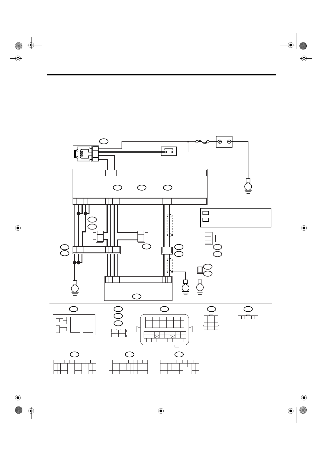
CD:DTC P2103 THROTTLE ACTUATOR CONTROL MOTOR CIRCUIT HIGH
DTC DETECTING CONDITION:
Immediately at fault recognition
CAUTION:
After repair or replacement of faulty parts, conduct Clear Memory Mode <Ref. to EN(H4SO 2.5)(diag)-
40, Clear Memory Mode.> and Inspection Mode <Ref. to EN(H4SO 2.5)(diag)-33, Inspection Mode.>.
WIRING DIAGRAM:
• EC, EK, EH, ER and K4 model
EN-03512
B362
E57
B362
B20
B21
E57
B122
B83
B138
1 2
7 8
3
4
5
6
1 2 3 4 5 6 7 8 9 10 11
12 13 14 15 16 17 18 19 20 21 22
23 24 25
34 35
36 37 38 39 40 41
48 49
50 51 52 53 54
42 43
44 45
46 47
26 27 28 29 30 31 32 33
1 2 3 4
5 6 7 8
1
2
7
8 9
5
6
3
4
10 11 12
19 20 21
29
30 31
13 14 15 16 17
27
28
18
22 23
24 25
26
1
2
7
8 9
5
6
3
4
10 11 12
19
20 21
29 30 31
13 14 15 16 17
27
28
18
22 23
24 25
26
32 33
34 35
1
2
8 9
5
6
3
4
10 11 12
19 20 21
29 30
31
13 14 15 16
17
27
28
18
22 23 24 25 26
7
32 33 34 35
B135
B:
B136
C:
B137
D:
BATTERY
MAIN RELAY
ELECTRONIC
THROTTLE
CONTROL RELAY
ELECTRONIC
THROTTLE CONTROL
SBF-7
B135
B:
B137
B136
D:
E1
B20
B83
C:
E
E
E
D6
B35
38
39
20
19
16
15
E2
B21
4
6
1
2
3
5
D4
D5
C35
C16
B1
B4
D1
D2
D3
36
35
37
C29
C18
ECM
5
8
7
6
36
B21
E2
E
B122 : RHD
B138 : LHD
1 2 3 4 5 6
B138 : RHD
B122 : LHD
1 2 3 4
5 6 7 8
9 10 11 12
14
13
15 16
*
: TERMINAL No. RANDOM ARRANGEMENT
1
*
: TERMINAL No. RANDOM ARRANGEMENT
AMONG 1,2,5, AND 6
2
*
1
*
2
*
1
*
1
*
1
*
2

EN(H4SO 2.5)(diag)-234
ENGINE (DIAGNOSTICS)
Diagnostic Procedure with Diagnostic Trouble Code (DTC)
• KA and KS model
NOTE:
Fuel injection system for KA and KS model is the same as 2.0 L model. Refer to EN(H4SO 2.0) section.
CE:DTC P2109 THROTTLE/PEDAL POSITION SENSOR “A” MINIMUM STOP
PERFORMANCE
NOTE:
For the diagnostic procedure, refer to DTC P2101. <Ref. to EN(H4SO 2.5)(diag)-224, DTC P2101 THROT-
TLE ACTUATOR CONTROL MOTOR CIRCUIT RANGE/PERFORMANCE, Diagnostic Procedure with Di-
agnostic Trouble Code (DTC).>
Step
Check
Yes
No
1
CHECK OPTION CODE.
Is the option code EC, EK, EH,
ER or K4?
Refer to EN(H4SO
2.0) section. <Ref.
to EN(H4SO
2.0)(diag)-64, List
of Diagnostic Trou-
ble Code (DTC).>
NOTE:
Fuel injection sys-
tem for KA and KS
model is the same
as 2.0 L model.
2
CHECK ELECTRONIC THROTTLE CON-
TROL RELAY.
1) Turn the ignition switch to OFF.
2) Remove the electronic throttle control relay.
3) Measure the resistance between electronic
throttle control relay terminals.
Terminals
No. 7 — No. 8:
Is the resistance more than 1
M
Ω?
Replace the elec-
tronic throttle con-
trol relay.
3
CHECK POWER SUPPLY SHORT CIRCUIT
OF ELECTRONIC THROTTLE CONTROL
RELAY.
1) Turn the ignition switch to ON.
2) Measure the voltage between electronic
throttle control relay connector and chassis
ground.
Connector & terminal
(B362) No. 7 (+) — Chassis ground (
−
):
Is the voltage more than 5 V?
Repair the power
supply short cir-
cuit of harness
between ECM and
electronic throttle
control relay.
4
CHECK HARNESS BETWEEN ECM AND
ELECTRONIC THROTTLE CONTROL RE-
LAY.
1) Turn the ignition switch to OFF.
2) Disconnect the connector from ECM.
3) Measure the resistance between ECM con-
nector and chassis ground.
Connector & terminal
(B135) No. 35 — Chassis ground:
Is the resistance more than 1
M
Ω?
Repair the poor
contact in ECM
connector.
Replace the ECM
if defective. <Ref.
to FU(H4SO 2.5)-
37, Engine Con-
trol Module
(ECM).>
Repair the ground
short circuit of har-
ness between
ECM and elec-
tronic throttle con-
trol relay.
EN(H4SO 2.5)(diag)-235
ENGINE (DIAGNOSTICS)
Diagnostic Procedure with Diagnostic Trouble Code (DTC)
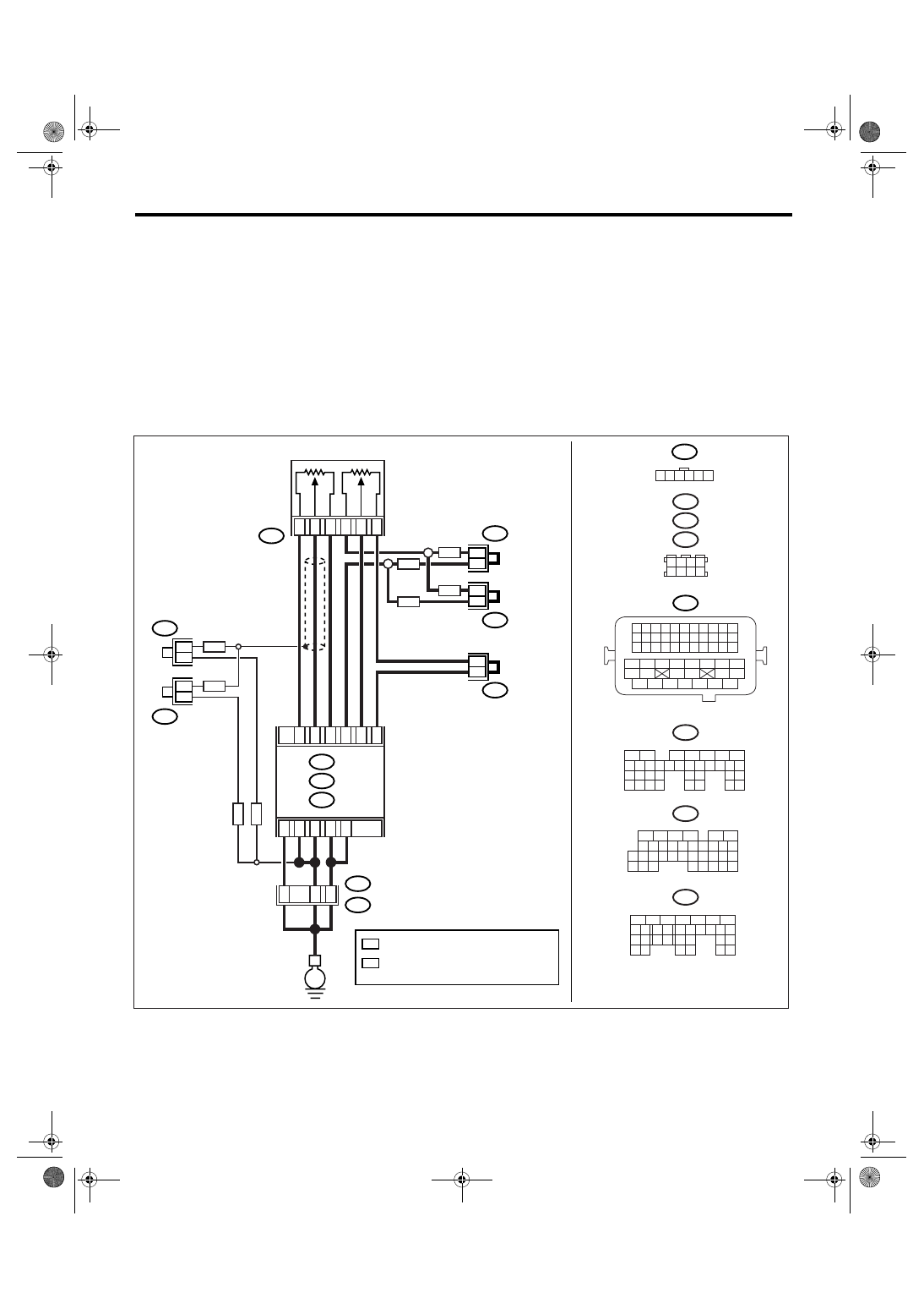
CF:DTC P2122 THROTTLE/PEDAL POSITION SENSOR/SWITCH “D” CIRCUIT
LOW INPUT
DTC DETECTING CONDITION:
Immediately at fault recognition
TROUBLE SYMPTOM:
• Erroneous idling
• Poor driving performance
CAUTION:
After repair or replacement of faulty parts, conduct Clear Memory Mode <Ref. to EN(H4SO 2.5)(diag)-
40, Clear Memory Mode.> and Inspection Mode <Ref. to EN(H4SO 2.5)(diag)-33, Inspection Mode.>.
WIRING DIAGRAM:
• EC, EK, EH, ER and K4 model
• KA and KS model
NOTE:
Fuel injection system for KA and KS model is the same as 2.0 L model. Refer to EN(H4SO 2.0) section.
EN-03468
B315
ACCELERATOR
PEDAL
POSITION
SENSOR
B138
1 2 3 4
5 6 7 8
MAIN
SUB
B21
1 2 3 4
12 13 14 15
5 6 7 8
16 17 18 19
9 10 11
20 21 22
23 24 25 26 27 28 29 30 31 32 33
35
34
37
36
39
38
41
40
43
42
44
45
47
46
49
48
51
50
53
52
54
B137
5
6
7
8
2
1
9
4
3
10
22 23
11 12 13 14 15
24 25
26
16 17
18 19 20 21
27
28 29
30 31
B136
5
6
7 8
2
1
9
4
3
10
24
22 23
25
11 12 13 14 15
26 27
28
16
17 18 19 20 21
33 34
29
32
30
31
35
B135
5
6
7
8
2
1
9
4
3
10
24
22 23
25
11 12 13 14 15
26 27
28
16 17 18 19
20 21
29 30 31
32 33
34 35
B:
C:
D:
B122
B83
1 2 3 4 5 6
E
C:
ECM
B136
B137
D:
B83
B315
3
5
4
1
2
6
C15
C17
C34
C16
C28
C35
D1
D2
B21
E2
B1
B138
B122
D3
B: B135
B4
37
36
35
B138
B122
LHD
LHD
RHD
RHD
RHD
LHD
RHD
LHD
*
*
1
1
*
2
*
2
*
2
*
2
*
1
*
1
*
1
*
1
*
: TERMINAL No. RANDOM ARRANGEMENT
1
*
: TERMINAL No. RANDOM ARRANGEMENT
AMONG 1,2,5, AND 6
2

EN(H4SO 2.5)(diag)-236
ENGINE (DIAGNOSTICS)
Diagnostic Procedure with Diagnostic Trouble Code (DTC)
Step
Check
Yes
No
1
CHECK OPTION CODE.
Is the option code EC, EK, EH,
ER or K4?
Refer to EN(H4SO
2.0) section. <Ref.
to EN(H4SO
2.0)(diag)-64, List
of Diagnostic Trou-
ble Code (DTC).>
NOTE:
Fuel injection sys-
tem for KA and KS
model is the same
as 2.0 L model.
2
CHECK ACCELERATOR PEDAL POSITION
SENSOR OUTPUT.
1) Turn the ignition switch to ON.
2) Read the data of main accelerator pedal
position sensor signal using Subaru Select
Monitor.
NOTE:
For detailed operation procedure, refer to
“READ CURRENT DATA FOR ENGINE”. <Ref.
to EN(H4SO 2.5)(diag)-25, Subaru Select Mon-
itor.>
Is the voltage more than 0.4 V? Go to step 3.
3
CHECK POOR CONTACT.
Check poor contact in connector between
ECM and accelerator pedal position sensor.
Is there poor contact?
Repair the poor
contact.
Temporary poor
contact occurred,
but it is normal at
present.
4
CHECK HARNESS BETWEEN ECM AND AC-
CELERATOR PEDAL POSITION SENSOR.
1) Turn the ignition switch to OFF.
2) Disconnect the connector from ECM.
3) Disconnect the connectors from accelerator
pedal position sensor.
4) Measure the resistance between ECM con-
nector and accelerator pedal position sensor
connector.
Connector & terminal
(B136) No. 17 — (B315) No. 5:
(B136) No. 15 — (B315) No. 3:
Is the resistance less than 1
Ω?
Repair the open
circuit of harness
connector.
5
CHECK HARNESS BETWEEN ECM AND AC-
CELERATOR PEDAL POSITION SENSOR.
Measure the resistance between ECM connec-
tor and chassis ground.
Connector & terminal
(B136) No. 17 — Chassis ground:
(B136) No. 15 — Chassis ground:
Is the resistance more than 1
M
Ω?
Repair the chas-
sis short circuit of
harness.
6
CHECK POWER SUPPLY OF ACCELERA-
TOR PEDAL POSITION SENSOR.
1) Connect the ECM connector.
2) Turn the ignition switch to ON.
3) Measure the voltage between accelerator
pedal position sensor connector and engine
ground.
Connector & terminal
(B315) No. 3 (+) — Engine ground (
−
):
Is the voltage 4.5 — 5.5 V?
Repair the poor
contact in ECM
connector.
Replace the ECM
if defective. <Ref.
to FU(H4SO 2.5)-
37, Engine Con-
trol Module
(ECM).>
7
CHECK ACCELERATOR PEDAL POSITION
SENSOR.
Measure the resistance of accelerator pedal
position sensor.
Terminals
No. 3 — No. 4:
Is the resistance 1.2 — 4.8
k
Ω?
Replace the accel-
erator pedal posi-
tion sensor.
Нет комментариевНе стесняйтесь поделиться с нами вашим ценным мнением.
Текст