Subaru Legacy (2005 year). Service manual — part 235
EN(H4SO 2.5)(diag)-225
ENGINE (DIAGNOSTICS)
Diagnostic Procedure with Diagnostic Trouble Code (DTC)
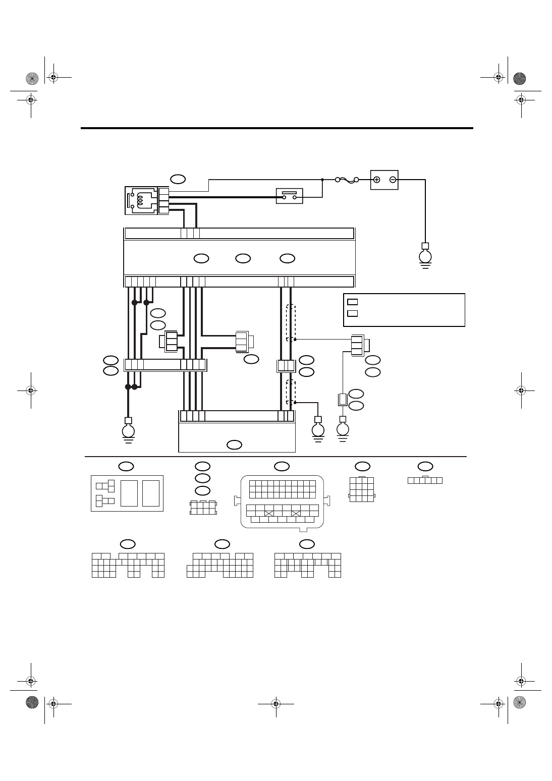
WIRING DIAGRAM:
• EC, EK, EH, ER and K4 model
• KA and KS model
NOTE:
Fuel injection system for KA and KS model is the same as 2.0 L model. Refer to EN(H4SO 2.0) section.
EN-03512
B362
E57
B362
B20
B21
E57
B122
B83
B138
1 2
7 8
3
4
5
6
1 2 3 4 5 6 7 8 9 10 11
12 13 14 15 16 17 18 19 20 21 22
23 24 25
34 35
36 37 38 39 40 41
48 49
50 51 52 53 54
42 43
44 45
46 47
26 27 28 29 30 31 32 33
1 2 3 4
5 6 7 8
1
2
7
8 9
5
6
3
4
10 11 12
19 20 21
29
30 31
13 14 15 16 17
27
28
18
22 23
24 25
26
1
2
7
8 9
5
6
3
4
10 11 12
19
20 21
29 30 31
13 14 15 16 17
27
28
18
22 23
24 25
26
32 33
34 35
1
2
8 9
5
6
3
4
10 11 12
19 20 21
29 30
31
13 14 15 16
17
27
28
18
22 23 24 25 26
7
32 33 34 35
B135
B:
B136
C:
B137
D:
BATTERY
MAIN RELAY
ELECTRONIC
THROTTLE
CONTROL RELAY
ELECTRONIC
THROTTLE CONTROL
SBF-7
B135
B:
B137
B136
D:
E1
B20
B83
C:
E
E
E
D6
B35
38
39
20
19
16
15
E2
B21
4
6
1
2
3
5
D4
D5
C35
C16
B1
B4
D1
D2
D3
36
35
37
C29
C18
ECM
5
8
7
6
36
B21
E2
E
B122 : RHD
B138 : LHD
1 2 3 4 5 6
B138 : RHD
B122 : LHD
1 2 3 4
5 6 7 8
9 10 11 12
14
13
15 16
*
: TERMINAL No. RANDOM ARRANGEMENT
1
*
: TERMINAL No. RANDOM ARRANGEMENT
AMONG 1,2,5, AND 6
2
*
1
*
2
*
1
*
1
*
1
*
2
EN(H4SO 2.5)(diag)-226
ENGINE (DIAGNOSTICS)
Diagnostic Procedure with Diagnostic Trouble Code (DTC)
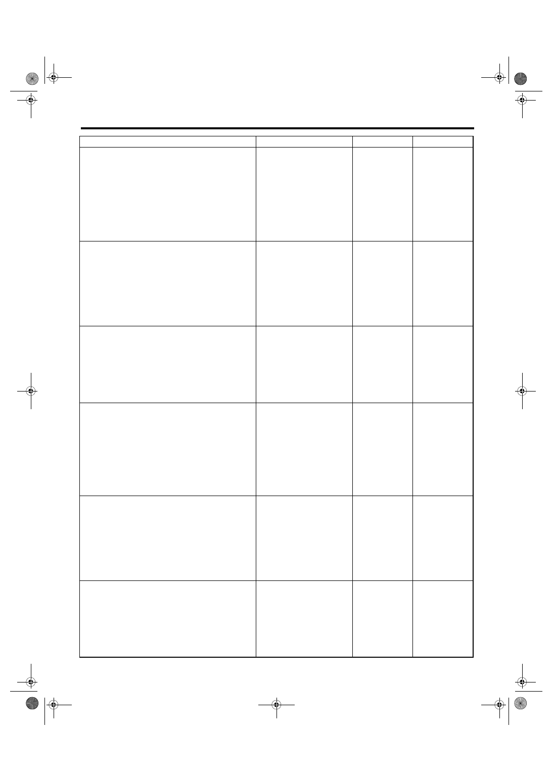
Step
Check
Yes
No
1
CHECK OPTION CODE.
Is the option code EC, EK, EH,
ER or K4?
Refer to EN(H4SO
2.0) section. <Ref.
to EN(H4SO
2.0)(diag)-64, List
of Diagnostic Trou-
ble Code (DTC).>
NOTE:
Fuel injection sys-
tem for KA and KS
model is the same
as 2.0 L model.
2
CHECK ELECTRONIC THROTTLE CON-
TROL RELAY.
1) Turn the ignition switch to OFF.
2) Remove the electronic throttle control relay.
3) Connect the battery to terminals No. 5 and
No. 6 of electronic throttle control relay.
4) Measure the resistance between electronic
throttle control relay terminals.
Terminals
No. 7 — No. 8:
Is the resistance less than 1
Ω?
Replace the elec-
tronic throttle con-
trol relay.
3
CHECK POWER SUPPLY OF ELECTRONIC
THROTTLE CONTROL RELAY.
1) Turn the ignition switch to ON.
2) Measure the voltage between electronic
throttle control relay connector and chassis
ground.
Connector & terminal
(B362) No. 8 (+) — Chassis ground (
−
):
(B362) No. 5 (+) — Chassis ground (
−
):
Is the voltage more than 10 V? Go to step 4.
Repair the open or
ground short cir-
cuit of power sup-
ply circuit.
4
CHECK HARNESS BETWEEN ECM AND
ELECTRONIC THROTTLE CONTROL RE-
LAY.
1) Turn the ignition switch to OFF.
2) Disconnect the connector from ECM.
3) Turn the ignition switch to ON.
4) Measure the voltage between electronic
throttle control relay connector and chassis
ground.
Connector & terminal
(B362) No. 6 (+) — Chassis ground (
−
):
Is the voltage more than 10 V? Repair the power
supply short cir-
cuit of harness
between ECM and
electronic throttle
control.
5
CHECK HARNESS BETWEEN ECM AND
ELECTRONIC THROTTLE CONTROL RE-
LAY.
1) Turn the ignition switch to OFF.
2) Measure the resistance between electronic
throttle control relay connector and chassis
ground.
Connector & terminal
(B362) No. 6 — Chassis ground:
(B362) No. 7 — Chassis ground:
Is the resistance more than 1
M
Ω?
Repair the ground
short circuit of har-
ness between
ECM and elec-
tronic throttle con-
trol relay.
6
CHECK HARNESS BETWEEN ECM AND
ELECTRONIC THROTTLE CONTROL RE-
LAY.
Measure the resistance between ECM connec-
tor and electronic throttle control relay connec-
tor.
Connector & terminal
(B135) No. 35 — (B362) No. 6:
(B137) No. 6 — (B362) No. 7:
Is the resistance less than 1
Ω?
Repair the open
circuit of harness
between ECM and
electronic throttle
control relay.

EN(H4SO 2.5)(diag)-227
ENGINE (DIAGNOSTICS)
Diagnostic Procedure with Diagnostic Trouble Code (DTC)
7
CHECK SENSOR OUTPUT.
1) Connect all the connectors.
2) Turn the ignition switch to ON.
3) Read the data of main throttle sensor signal
using Subaru Select Monitor.
NOTE:
For detailed operation procedure, refer to
“READ CURRENT DATA FOR ENGINE”. <Ref.
to EN(H4SO 2.5)(diag)-25, Subaru Select Mon-
itor.>
Is the voltage more than 0.4 V? Go to step 8.
8
CHECK SENSOR OUTPUT.
Read the data of sub throttle sensor signal
using Subaru Select Monitor.
NOTE:
For detailed operation procedure, refer to
“READ CURRENT DATA FOR ENGINE”. <Ref.
to EN(H4SO 2.5)(diag)-25, Subaru Select Mon-
itor.>
Is the voltage more than 0.8 V? Go to step 9.
9
CHECK POOR CONTACT.
Check poor contact in connector between
ECM and electronic throttle control.
Is there poor contact?
Repair the poor
contact.
10
CHECK HARNESS BETWEEN ECM AND
ELECTRONIC THROTTLE CONTROL.
1) Turn the ignition switch to OFF.
2) Disconnect the connector from ECM.
3) Disconnect the connectors from electronic
throttle control.
4) Measure the resistance between ECM con-
nector and electronic throttle control connector.
Connector & terminal
(B136) No. 18 — (E57) No. 6:
(B136) No. 29 — (E57) No. 4:
(B136) No. 16 — (E57) No. 5:
Is the resistance less than 1
Ω?
Repair the open
circuit of harness
connector.
11
CHECK HARNESS BETWEEN ECM AND
ELECTRONIC THROTTLE CONTROL.
Measure the resistance between ECM connec-
tor and chassis ground.
Connector & terminal
(B136) No. 16 — Chassis ground:
(B136) No. 18 — Chassis ground:
(B136) No. 29 — Chassis ground:
Is the resistance more than 1
M
Ω?
Repair the ground
short circuit of har-
ness.
12
CHECK SENSOR POWER SUPPLY.
1) Connect the ECM connector.
2) Turn the ignition switch to ON.
3) Measure the voltage between electronic
throttle control connector and engine ground.
Connector & terminal
(E57) No. 5 (+) — Engine ground (
−
):
Is the voltage 4.5 — 5.5 V?
Repair the poor
contact in ECM
connector.
Replace the ECM
if defective. <Ref.
to FU(H4SO 2.5)-
37, Engine Con-
trol Module
(ECM).>
13
CHECK SHORT CIRCUIT INSIDE THE ECM.
1) Turn the ignition switch to OFF.
2) Measure the resistance between electronic
throttle control connector and engine ground.
Connector & terminal
(E57) No. 6 — Engine ground:
(E57) No. 4 — Engine ground:
Is the resistance more than 10
Ω?
Repair the poor
contact in ECM
connector.
Replace the ECM
if defective. <Ref.
to FU(H4SO 2.5)-
37, Engine Con-
trol Module
(ECM).>
Step
Check
Yes
No

EN(H4SO 2.5)(diag)-228
ENGINE (DIAGNOSTICS)
Diagnostic Procedure with Diagnostic Trouble Code (DTC)
14
CHECK SENSOR OUTPUT.
1) Connect all the connectors.
2) Turn the ignition switch to ON.
3) Read the data of main throttle sensor signal
using Subaru Select Monitor.
NOTE:
For detailed operation procedure, refer to
“READ CURRENT DATA FOR ENGINE”. <Ref.
to EN(H4SO 2.5)(diag)-25, Subaru Select Mon-
itor.>
Is the voltage less than 4.63
V?
15
CHECK SENSOR OUTPUT.
Read the data of sub throttle sensor signal
using Subaru Select Monitor.
NOTE:
For detailed operation procedure, refer to
“READ CURRENT DATA FOR ENGINE”. <Ref.
to EN(H4SO 2.5)(diag)-25, Subaru Select Mon-
itor.>
Is the voltage less than 4.73
V?
16
CHECK POOR CONTACT.
Check poor contact in connector between
ECM and electronic throttle control.
Is there poor contact?
Repair the poor
contact.
17
CHECK HARNESS BETWEEN ECM AND
ELECTRONIC THROTTLE CONTROL.
1) Turn the ignition switch to OFF.
2) Disconnect the connector from ECM.
3) Disconnect the connectors from electronic
throttle control.
4) Measure the resistance between ECM con-
nector and electronic throttle control connector.
Connector & terminal
(B136) No. 35 — (E57) No. 3:
(B136) No. 18 — (E57) No. 6:
(B136) No. 29 — (E57) No. 4:
Is the resistance less than 1
Ω?
Repair the open
circuit of harness
connector.
18
CHECK HARNESS BETWEEN ECM AND
ELECTRONIC THROTTLE CONTROL.
1) Connect the ECM connector.
2) Measure the resistance between electronic
throttle control connector and engine ground.
Connector & terminal
(E57) No. 3 — Engine ground:
Is the resistance less than 5
Ω?
Repair the poor
contact in ECM
connector.
Replace the ECM
if defective. <Ref.
to FU(H4SO 2.5)-
37, Engine Con-
trol Module
(ECM).>
19
CHECK HARNESS BETWEEN ECM AND
ELECTRONIC THROTTLE CONTROL.
1) Turn the ignition switch to ON.
2) Measure the voltage between electronic
throttle control connector and engine ground.
Connector & terminal
(E57) No. 5 (+) — Engine ground (
−
):
Is the voltage less than 10 V?
Repair the battery
short circuit of har-
ness between
ECM connector
and electronic
throttle control
connector.
20
CHECK HARNESS BETWEEN ECM AND
ELECTRONIC THROTTLE CONTROL.
Measure the voltage between electronic throt-
tle control connector and engine ground.
Connector & terminal
(E57) No. 6 (+) — Engine ground (
−
):
(E57) No. 4 (+) — Engine ground (
−
):
Is the voltage less than 10 V?
Repair the short
circuit of harness
between ECM
connector and
electronic throttle
control connector.
Step
Check
Yes
No
Нет комментариевНе стесняйтесь поделиться с нами вашим ценным мнением.
Текст