Subaru Legacy (2005 year). Service manual — part 323
EN(H4DOTC)(diag)-61
ENGINE (DIAGNOSTICS)
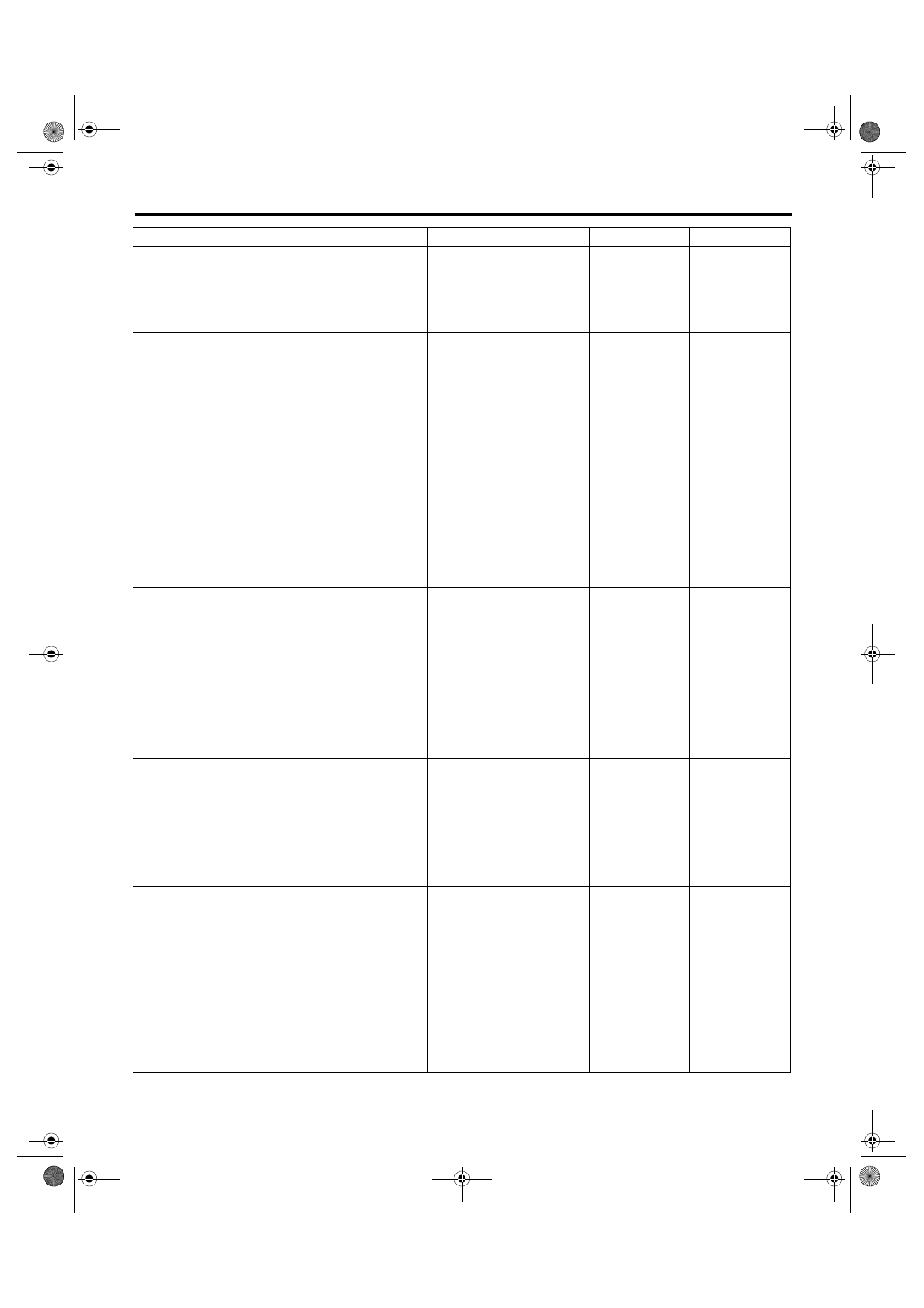
Diagnostics for Engine Starting Failure
Step
Check
Yes
No
1
CHECK OPERATION OF EACH FUEL INJEC-
TOR.
While cranking the engine, check each fuel
injector emits operating sound. Use a sound
scope or attach a screwdriver to the injector for
this check.
Does the fuel injector emit
operating sound?
Check the fuel
pressure. <Ref. to
ME(H4DOTC)-27,
INSPECTION,
Fuel Pressure.>
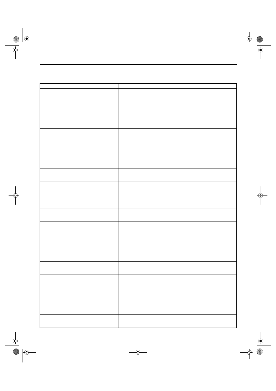
2
CHECK POWER SUPPLY TO EACH FUEL
INJECTOR.
1) Turn the ignition switch to OFF.
2) Disconnect the connector from fuel injector.
3) Turn the ignition switch to ON.
4) Measure the power supply voltage between
fuel injector terminal and engine ground.
Connector & terminal
#1 (E5) No. 2 (+) — Engine ground (
−
):
#2 (E16) No. 2 (+) — Engine ground (
−
):
#3 (E6) No. 2 (+) — Engine ground (
−
):
#4 (E17) No. 2 (+) — Engine ground (
−
):
Is the voltage more than 10 V? Go to step 3.
Repair the har-
ness and connec-
tor.
NOTE:
In this case, repair
the following:
• Open circuit of
harness between
main relay and fuel
injector connector
• Poor contact in
main relay connec-
tor
• Poor contact in
coupling connector
• Poor contact in
fuel injector con-
nector
3
CHECK HARNESS BETWEEN ECM AND
FUEL INJECTOR CONNECTOR.
1) Disconnect the connector from ECM.
2) Measure the resistance of harness
between ECM and fuel injector connector.
Connector & terminal
(B136) No. 6 — (E5) No. 1:
(B136) No. 5 — (E16) No. 1:
(B136) No. 4 — (E6) No. 1:
(B136) No. 3 — (E17) No. 1:
Is the resistance less than 1
Ω?
Repair the har-
ness and connec-
tor.
NOTE:
In this case, repair
the following:
• Open circuit of
harness between
ECM and fuel
injector connector
• Poor contact in
coupling connector
4
CHECK HARNESS BETWEEN ECM AND
FUEL INJECTOR CONNECTOR.
Measure the resistance of harness between
ECM and chassis ground.
Connector & terminal
(B136) No. 6 — Chassis ground:
(B136) No. 5 — Chassis ground:
(B136) No. 4 — Chassis ground:
(B136) No. 3 — Chassis ground:
Is the resistance more than 1
M
Ω?
Repair the ground
short circuit of har-
ness between
ECM and fuel
injector connector.
5
CHECK EACH FUEL INJECTOR.
1) Turn the ignition switch to OFF.
2) Measure the resistance between each fuel
injector terminals.
Terminals
No. 1 — No. 2:
Is the resistance 5 — 20
Ω?
Replace the faulty
fuel injector.
6
CHECK POOR CONTACT.
Check poor contact in ECM connector.
Is there poor contact in ECM
connector?
Repair the poor
contact in ECM
connector.
Inspection using
“General Diagnos-
tic Table”. <Ref. to
EN(H4DOTC)(diag
)-213, INSPEC-
TION, General
Diagnostic Table.>
EN(H4DOTC)(diag)-62
ENGINE (DIAGNOSTICS)
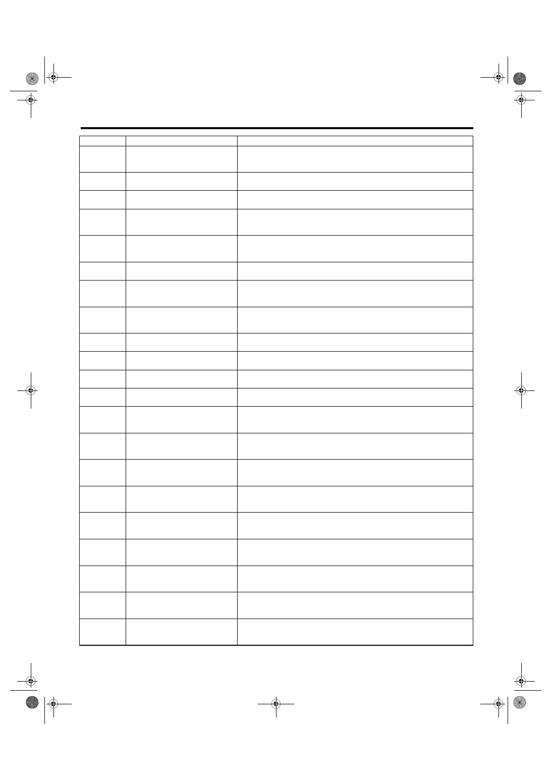
List of Diagnostic Trouble Code (DTC)
17.List of Diagnostic Trouble Code (DTC)
A: LIST
DTC
Item
Reference
P0031
HO2S Heater Control Circuit Low
(Bank 1 Sensor 1)
P0032
HO2S Heater Control Circuit High
(Bank 1 Sensor 1)
P0037
HO2S Heater Control Circuit Low
(Bank 1 Sensor 2)
P0038
HO2S Heater Control Circuit High
(Bank 1 Sensor 2)
P0102
Mass or Volume Air Flow Circuit
Low Input
P0103
Mass or Volume Air Flow Circuit
High Input
P0107
Manifold Absolute Pressure/Baro-
metric Pressure Circuit Low Input
P0108
Manifold Absolute Pressure/Baro-
metric Pressure Circuit High Input
P0112
Intake Air Temperature Sensor 1
Circuit Low
P0113
Intake Air Temperature Sensor 1
Circuit High
P0117
Engine Coolant Temperature Cir-
cuit Low
P0118
Engine Coolant Temperature Cir-
cuit High
P0122
Throttle/Pedal Position Sensor/
Switch “A” Circuit Low
P0123
Throttle/Pedal Position Sensor/
Switch “A” Circuit High
P0131
O2 Sensor Circuit Low Voltage
(Bank 1 Sensor 1)
P0132
O2 Sensor Circuit High Voltage
(Bank 1 Sensor 1)
P0134
O2 Sensor Circuit No Activity
Detected (Bank 1 Sensor 1)
P0137
O2 Sensor Circuit Low Voltage
(Bank 1 Sensor 2)
EN(H4DOTC)(diag)-63
ENGINE (DIAGNOSTICS)
List of Diagnostic Trouble Code (DTC)
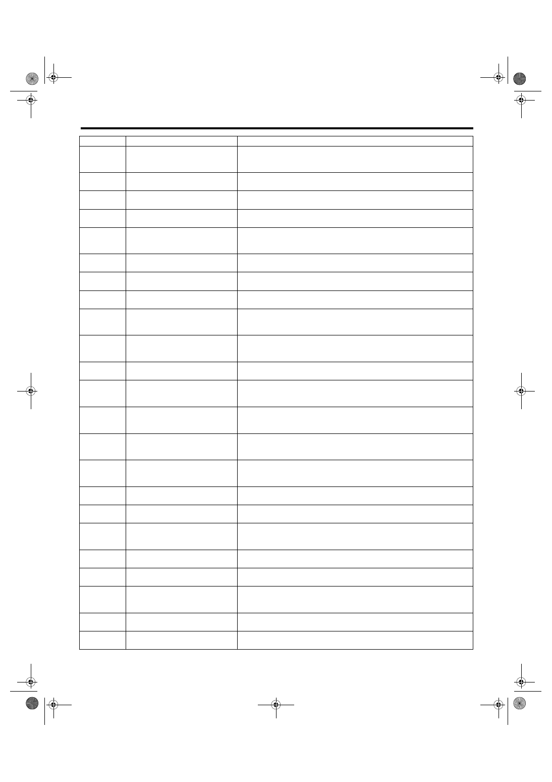
P0138
O2 Sensor Circuit High Voltage
(Bank 1 Sensor 2)
P0171
System Too Lean (Bank 1)
P0172
System Too Rich (Bank 1)
P0222
Throttle/Pedal Position Sensor/
Switch “B” Circuit Low
P0223
Throttle/Pedal Position Sensor/
Switch “B” Circuit High
P0230
Fuel Pump Primary Circuit
P0245
Turbo/Super Charger Wastegate
Solenoid “A” Low
P0246
Turbo/Super Charger Wastegate
Solenoid “A” High
P0261
Cylinder 1 Injector Circuit Low
P0264
Cylinder 2 Injector Circuit Low
P0267
Cylinder 3 Injector Circuit Low
P0270
Cylinder 4 Injector Circuit Low
P0327
Knock Sensor 1 Circuit Low (Bank
1 or Single Sensor)
P0328
Knock Sensor 1 Circuit High (Bank
1 or Single Sensor)
P0335
Crankshaft Position Sensor “A” Cir-
cuit
P0340
Camshaft Position Sensor “A” Cir-
cuit (Bank 1 or Single Sensor)
P0345
Camshaft Position Sensor “A” Cir-
cuit (Bank 2)
P0350
Ignition Coil Primary/Secondary
Circuit
P0365
Camshaft Position Sensor “B” Cir-
cuit (Bank 1)
P0390
Camshaft Position Sensor “B” Cir-
cuit (Bank 2)
P0458
Evaporative Emission System
Purge Control Valve Circuit Low
DTC
Item
Reference
EN(H4DOTC)(diag)-64
ENGINE (DIAGNOSTICS)
List of Diagnostic Trouble Code (DTC)
P0459
Evaporative Emission System
Purge Control Valve Circuit High
P0500
Vehicle Speed Sensor “A”
P0512
Starter Request Circuit
P0513
Incorrect Immobilizer Key
P0519
Idle Air Control System Perfor-
mance
P0562
System Voltage Low
P0563
System Voltage High
P0600
Serial Communication Link
P0604
Internal Control Module Random
Access Memory (RAM) Error
P0605
Internal Control Module Read Only
Memory (ROM) Error
P0607
Control Module Performance
P0638
Throttle Actuator Control Range/
Performance (Bank 1)
P0700
Transmission Control System (MIL
Request)
P0851
Park/Neutral Switch Input Circuit
Low
P0852
Park/Neutral Switch Input Circuit
High
P1160
Return Spring Failure
P1518
Starter Switch Circuit Low Input
P1560
Back-up Voltage Circuit Malfunc-
tion
P1570
Antenna
<Ref. to IM(diag)-18, DTC P1570 ANTENNA, Diagnostic Procedure with
Diagnostic Trouble Code (DTC).>
P1571
Reference Code Incompatibility
P1572
IMM Circuit Failure (Except
Antenna Circuit)
P1574
Key Communication Failure
P1576
EGI Control Module EEPROM
DTC
Item
Reference
Нет комментариевНе стесняйтесь поделиться с нами вашим ценным мнением.
Текст