Subaru Legacy (2005 year). Service manual — part 292
EX(H4DOTC)-11
EXHAUST
Rear Exhaust Pipe
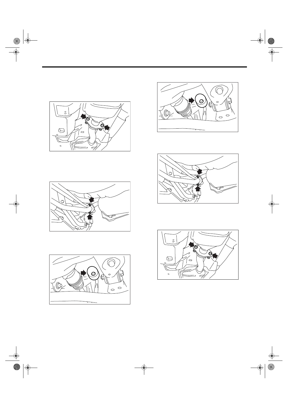
5. Rear Exhaust Pipe
A: REMOVAL
1) Lift-up the vehicle.
2) Separate the rear exhaust pipe from center ex-
haust pipe.
3) Separate the rear exhaust pipe from both muf-
flers.
CAUTION:
Be careful not to pull down the rear exhaust
pipe.
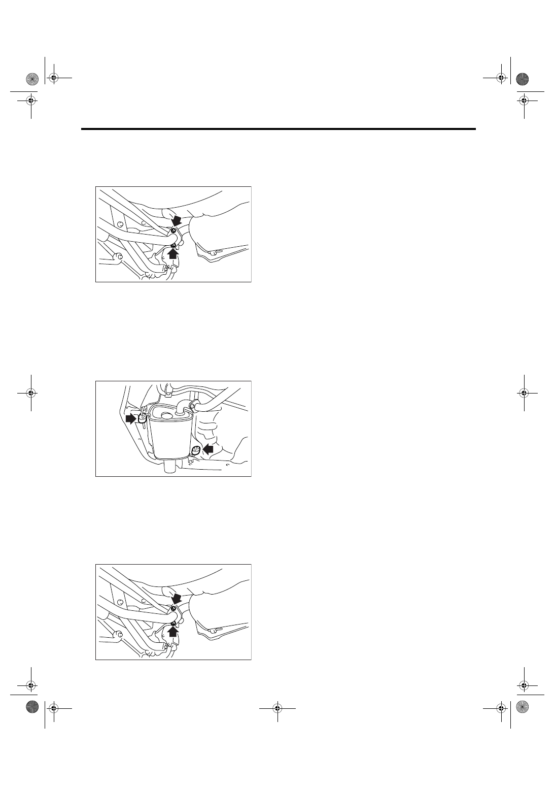
4) Apply a coat of spray type lubricant to the mating
area of cushion rubber.
5) Remove the rear exhaust pipe bracket from
cushion rubber.
B: INSTALLATION
NOTE:
Use a new gasket and self-locking nut.
1) Apply a coat of spray type lubricant to the mating
area of cushion rubber.
2) Install the rear exhaust pipe bracket to cushion
rubber.
3) Install the rear exhaust pipe to both mufflers.
Tightening torque:
48 N
⋅
m (4.9 kgf-m, 35.4 ft-lb)
4) Install the rear exhaust pipe to center exhaust
pipe.
Tightening torque:
18 N
⋅
m (1.8 kgf-m, 13.3 ft-lb)
5) Lower the vehicle.
C: INSPECTION
1) Check the connections and welds for exhaust
leaks.
2) Check for hole or rust.
3) Check the cushion rubber for wear or crack.
EX-02015
EX-00210
EX-00219
EX-00219
EX-00210
EX-02015
EX(H4DOTC)-12
EXHAUST
Muffler
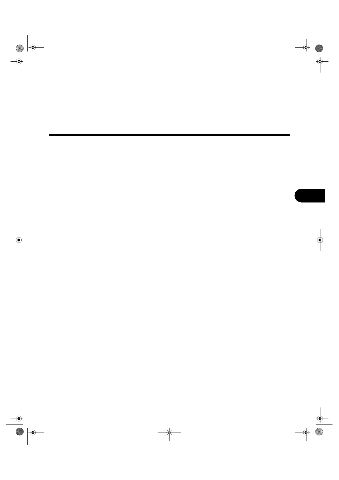
6. Muffler
A: REMOVAL
1) Separate the muffler (RH) from rear exhaust
pipe.
2) Remove the cushion rubbers, and detach the
muffler.
CAUTION:
Be careful not to drop the muffler during remov-
al.
NOTE:
To facilitate removal, apply a coat of spray type lu-
bricant to the mating area of cushion rubbers in ad-
vance.
3) Perform the same procedure for muffler (LH).
B: INSTALLATION
Install in the reverse order of removal.
NOTE:
Use a new gasket and self-locking nut.
Tightening torque:
48 N
⋅
m (4.9 kgf-m, 35.4 ft-lb)
C: INSPECTION
1) Check the connections and welds for exhaust
leaks.
2) Check for hole or rust.
3) Check the cushion rubber for wear or crack.
EX-00210
EX-00211
EX-00210
COOLING
CO(H4DOTC)
Page
General Description . . . . . . . . . . . . . . . . . . . . . 2
Radiator Fan System . . . . . . . . . . . . . . . . . . . . ..8
Engine Coolant. . . . . . . . . . . . . . . . . . . . . . ..13
Water Pump . . . . . . . . . . . . . . . . . . . . . . . ..15
Thermostat . . . . . . . . . . . . . . . . . . . . . . . . 17
Radiator. . . . . . . . . . . . . . . . . . . . . . . . . .19
Radiator Cap . . . . . . . . . . . . . . . . . . . . . . . .23
Radiator Main Fan and Fan Motor . . . . . . . . . . . . . . . 24
Radiator Sub Fan and Fan Motor. . . . . . . . . . . . . . . ..27
Reservoir Tank. . . . . . . . . . . . . . . . . . . . . . ..30
Coolant Filler Tank . . . . . . . . . . . . . . . . . . . . . 31
Engine Cooling System Trouble in General . . . . . . . . . . . ..32
CO(H4DOTC)-2
COOLING
General Description
1. General Description
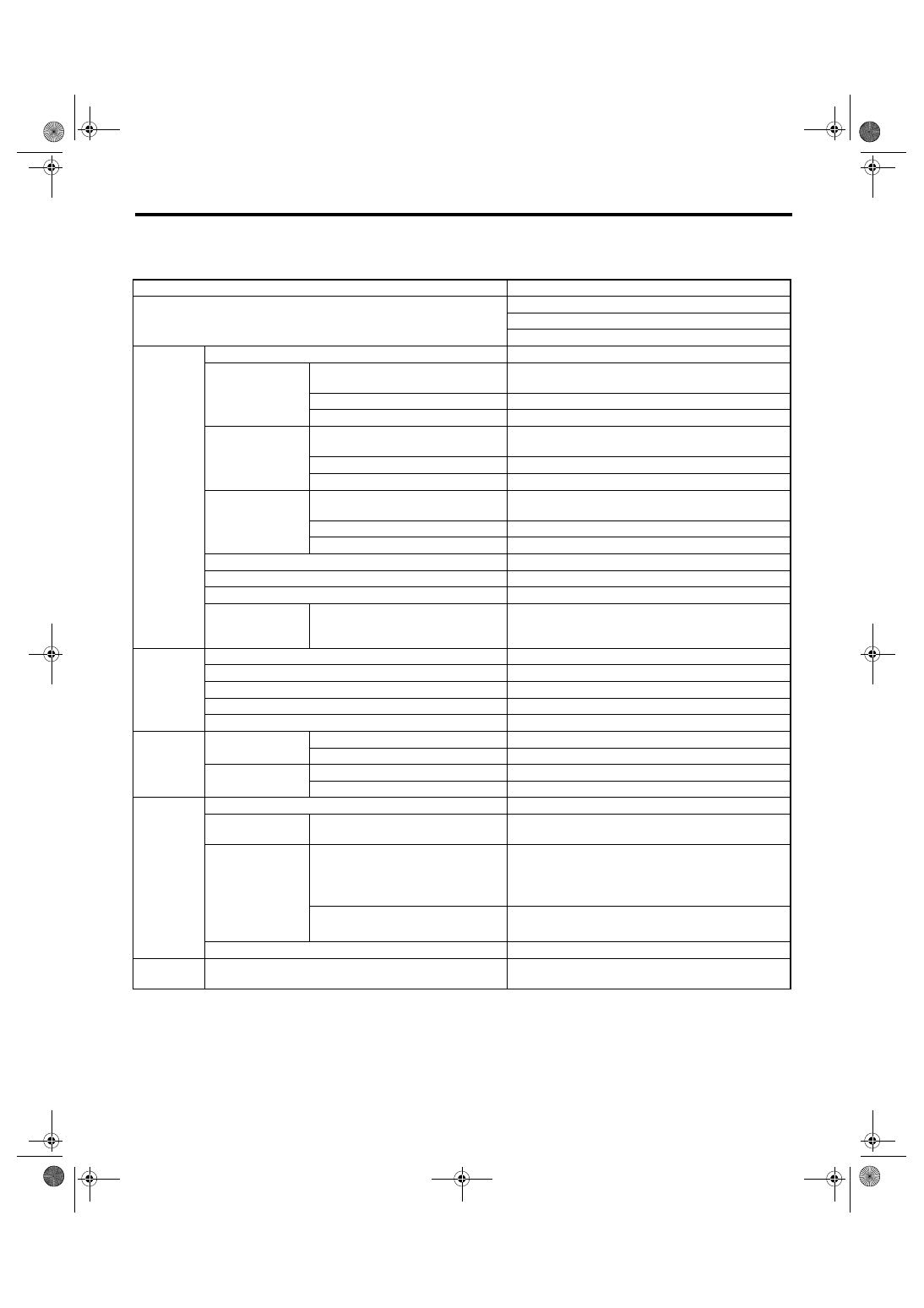
A: SPECIFICATION
Cooling system
Electric fan + Forced engine coolant circulation system
Total engine coolant capacity
2 (US qt, Imp qt)
AT model (with ATF warmer): 7.7 (8.1, 7.1)
AT model (without ATF warmer): 7.3 (7.7, 6.4)
MT model: 7.4 (7.8, 6.5)
Water pump
Type
Centrifugal impeller type
Discharge perfor-
mance I
Discharge rate
2 (US gal, Imp gal)
/min
20 (5.3, 4.4)
Pump speed — Discharge pressure
760 rpm — 2.9 kPa (0.3 mAq)
Engine coolant temperature
80
°C (176°F)
Discharge perfor-
mance II
Discharge rate
2 (US gal, Imp gal)
/min
100 (26.4, 22.0)
Pump speed — Discharge pressure
3,000 rpm — 49.0 kPa (5.0 mAq)
Engine coolant temperature
80
°C (176°F)
Discharge perfor-
mance III
Discharge rate
2 (US gal, Imp gal)
/min
200 (52.8, 44.0)
Pump speed — Discharge pressure
6,000 rpm — 225.4 kPa (23.0 mAq)
Engine coolant temperature
80
°C (176°F)
Impeller diameter
mm (in)
76 (2.99)
Number of impeller vanes
8
Pump pulley diameter
mm (in)
60 (2.36)
Clearance
between impeller
and case
Standard
mm (in)
0.5 — 1.5 (0.020 — 0.059)
Thermostat
Type
Wax pellet type
Starting temperature to open
76 — 80
°C (169 — 176°F)
Fully opens
91
°C (196°F)
Valve lift
mm (in)
9.0 (0.354) or more
Valve bore
mm (in)
35 (1.38)
Radiator fan
Motor input
Main fan
W
90
Sub fan
W
90
Fan diameter /
Blades
Main fan
300 mm (11.8 in) / 4
Sub fan
300 mm (11.8 in) / 5
Radiator
Type
Down flow
Core dimensions
Width
× Height ×Thick-
ness
mm (in)
687.4
× 340 × 16 (27.06 × 13.39 × 0.63)
Pressure range in
which cap valve is
open
Coolant filler tank side
Above: 108
±15
(1.1
±0.15, 16±2)
kPa (kgf/cm
2
, psi)
Below:
−1.0 — −4.9
(
−0.01 — −0.05, −0.1 — −0.7)
Radiator side
Above only: 137
±14.7
(1.40
±0.15, 20±2.1)
kPa (kgf/cm
2
, psi)
Fins
Corrugated fin type
Reservoir
tank
Capacity
2 (US qt, Imp qt)
0.45 (0.48, 0.40)
Нет комментариевНе стесняйтесь поделиться с нами вашим ценным мнением.
Текст