Subaru Legacy (2005 year). Service manual — part 606
5AT(diag)-15
AUTOMATIC TRANSMISSION (DIAGNOSTICS)
Transmission Control Module (TCM) I/O Signal
H&LR/C oil pressure
switch input
B55
8
While driving at 2nd of
manual mode
Power supply
voltage
—
While driving at 3rd — 5th
of manual mode
Approx. 0 V
Front vehicle speed sen-
sor input
B55
7
While driving at 2nd and
20 km/h (12 MPH) of man-
ual mode
Approx. 140 —
170 rpm
—
While driving at 4th and 80
km/h (50 MPH) of manual
mode
Approx. 560 —
680 rpm
Lateral G sensor power
supply
B55
6
Ignition switch ON
4.75 — 5.25 V
—
Lateral G sensor signal
input
B55
5
Ignition switch ON, Engine
ON, Flat value
2.0 — 3.0 V
—
Inhibitor switch 1 input
B55
4
Ignition switch ON, “P”
range
4.0 — 5.0 V
—
Ignition switch ON, “N”
range
1.5 V or less
Inhibitor switch 2 input
B55
3
Ignition switch ON, “P”
range
4.0 — 5.0 V
—
Ignition switch ON, “D”
range
1.5 V or less
Accessory power supply
B55
2
Accessory switch ON
Power supply
voltage
—
Accessory switch OFF
Approx. 0 V
Ignition power supply
B55
1
Ignition switch ON
Power supply
voltage
—
Ignition switch OFF
Approx. 0 V
Rear vehicle speed sen-
sor input
B55
18
While driving at 2nd and
20 km/h (12 MPH) of man-
ual mode
Approx. 190 —
230 rpm
—
While driving at 4th and 80
km/h (50 MPH) of manual
mode
Approx. 760 —
920 rpm
Fr/B oil pressure switch
input
B55
17
Ignition switch ON, Engine
ON, While driving at other
than 4th
Approx. 0 V
—
Ignition switch ON, Engine
ON, While driving at 4th
Power supply
voltage
Turbine speed sensor 1
input
B55
16
2nd of manual mode, Tur-
bine speed sensor is
2,000 rpm (Read from
Subaru Select Monitor)
Approx. 0 rpm
—
Use the Subaru
Select Monitor.
4th of manual mode, Tur-
bine speed sensor is
2,000 rpm (Read from
Subaru Select Monitor)
Approx. 1,900
— 2,100 rpm
Use the Subaru
Select Monitor.
Range lock solenoid out-
put
B55
15
Ignition switch ON, While
stopping at “D” range
Approx. Power
Supply Voltage
− 1.2 V
7 — 21
Ω
Ignition switch ON, Vehicle
speed at least 20 km/h (12
MPH)
Approx. 0 V
Item
Connector
No.
Ter-
min
al
No.
Measuring conditions
Voltage (V)
Resistance
between termi-
nal and chassis
ground
Remarks

5AT(diag)-16
AUTOMATIC TRANSMISSION (DIAGNOSTICS)
Transmission Control Module (TCM) I/O Signal
Inhibitor switch 3 input
B55
14
Ignition switch ON, “R”
range
4.0 — 5.0 V
—
Ignition switch ON, “D”
range
1.5 V or less
Inhibitor switch 4 input
B55
13
Ignition switch ON, “P”
range
4.0 — 5.0 V
—
Ignition switch ON, “D”
range
1.5 V or less
Control valve communi-
cation line
B55
12
—
—
—
Back-up light relay out-
put
B55
11
Ignition switch ON, “R”
range
1.5 V
Approx. 90 —
110
Ω (ATF tem-
perature 25
°C
(77
°F))
Ignition switch ON, Other
than “R” range
Power supply
voltage
Ignition power supply
B55
10
Ignition switch ON
Power supply
voltage
—
Ignition switch OFF
Approx. 0 V
AWD solenoid output
B55
23
Engine ON, “P” range or
“N” range, Accelerator
OFF
Approx. 0 V
3 — 9
Ω (ATF
temperature
20
°C (68°F))
Driving fre-
quency 750 —
850 Hz
Engine ON, “D” range,
Accelerator OFF, Brake
ON
Approx. 2.0 —
3.0 V
Turbine speed sensor 2
input
B55
22
2nd of manual mode, Tur-
bine speed sensor is
2,000 rpm (Read from
Subaru Select Monitor)
Approx. 1,300
— 1,500 rpm
Use the Subaru
Select Monitor.
4th of manual mode, Tur-
bine speed sensor is
2,000 rpm (Read from
Subaru Select Monitor)
Approx. 1,900
— 2,100 rpm
—
Use the Subaru
Select Monitor.
Control GND
B55
21
Always
Approx. 0 V
—
Inhibitor switch 3 open
circuit monitor input
B55
20
Ignition switch ON, “R”
range
4.0 — 5.0 V
—
Ignition switch ON, “D”
range
1.5 V or less
PN signal output
B55
19
Ignition switch ON, Other
than “P” range or “N”
range
Power supply
voltage
—
ECM should
connected cor-
rectly
Ignition switch ON, “P”
range or “N” range
0 — 1.0 V
—
Item
Connector
No.
Ter-
min
al
No.
Measuring conditions
Voltage (V)
Resistance
between termi-
nal and chassis
ground
Remarks
5AT(diag)-17
AUTOMATIC TRANSMISSION (DIAGNOSTICS)
Subaru Select Monitor
6. Subaru Select Monitor
A: OPERATION
1. READ DIAGNOSTIC TROUBLE CODE
(DTC)
1) Prepare the Subaru Select Monitor kit.
2) Connect the diagnosis cable to Subaru Select
Monitor.
3) Insert the cartridge to Subaru Select Monitor.
<Ref. to 5AT(diag)-6, PREPARATION TOOL, Gen-
eral Description.>
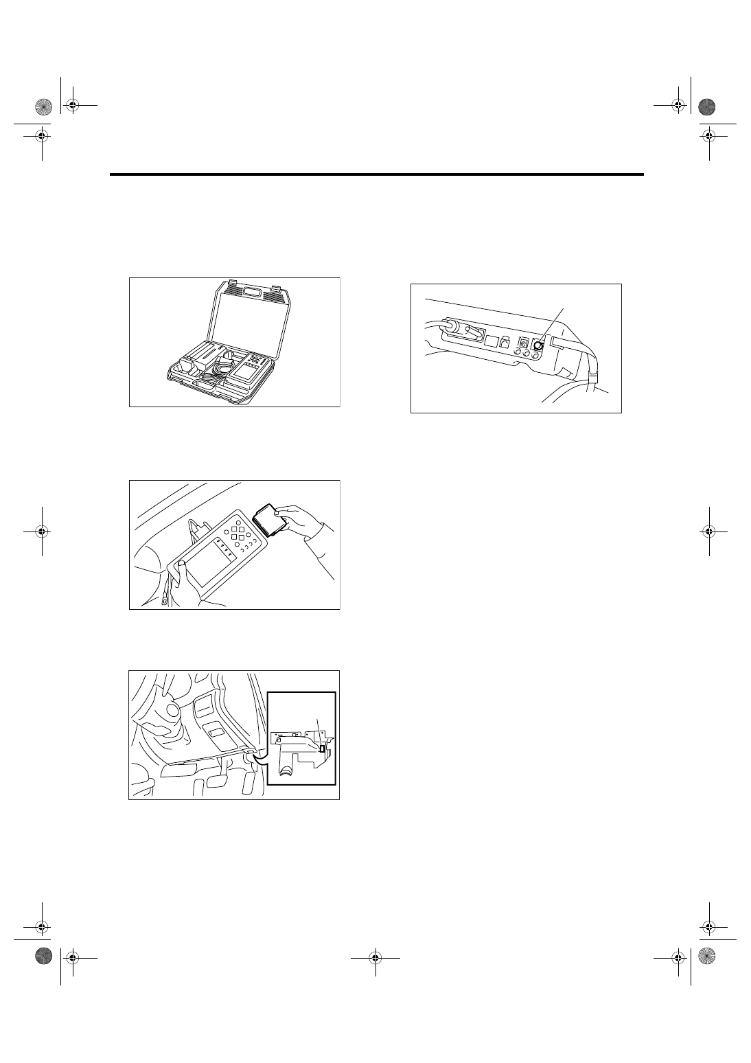
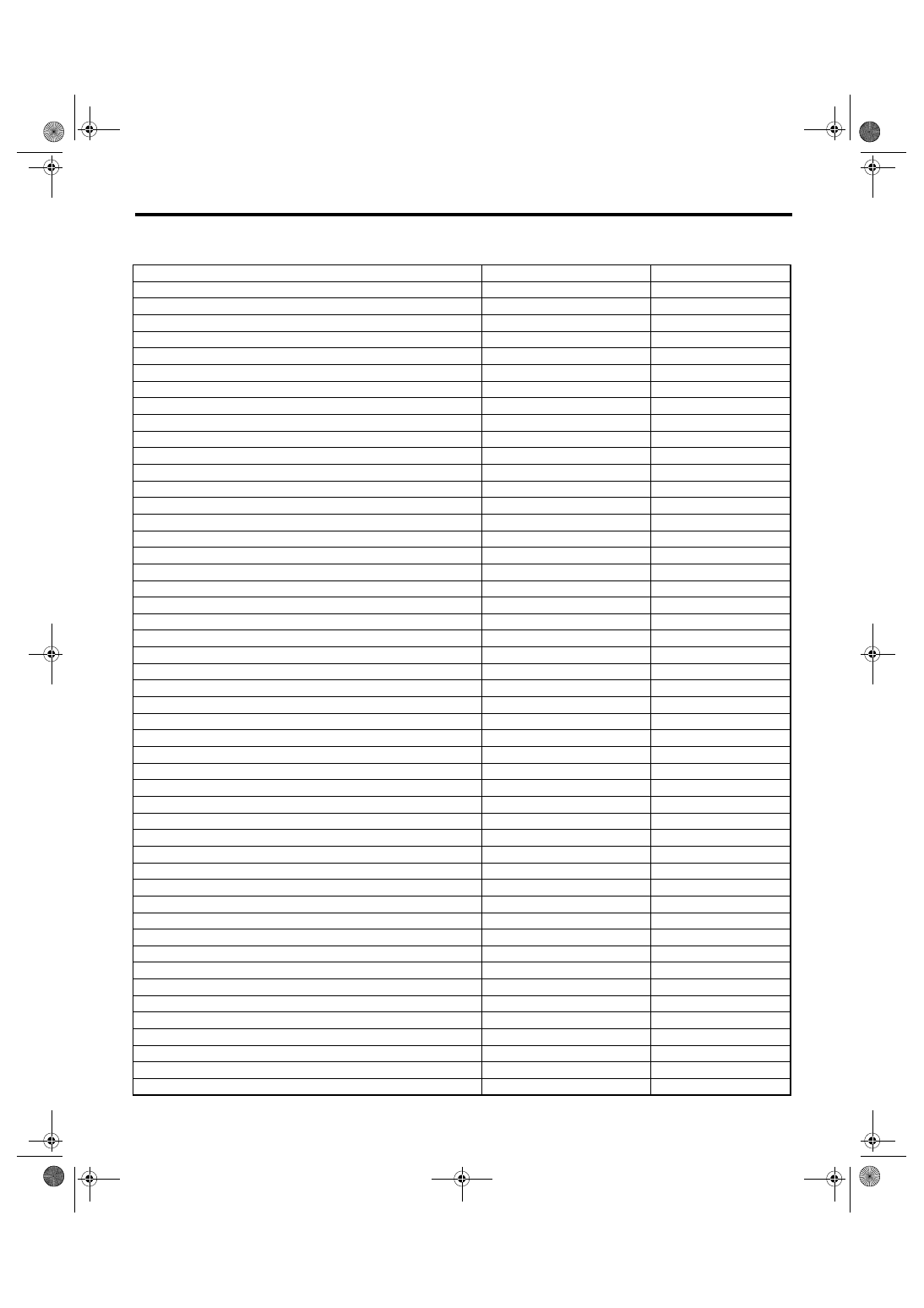
4) Connect the Subaru Select Monitor to data link
connector.
(1) Data link connector is located in the lower
portion of instrument panel (on the driver’s side).
(2) Connect the diagnosis cable to data link
connector.
NOTE:
Do not connect scan tools except Subaru Select
Monitor.
5) Turn the ignition switch to ON (engine OFF), and
turn the Subaru Select Monitor power switch to ON.
6) On the «Main Menu» display screen, select the
{Each System Check} and press the [YES] key.
7) On the «System Selection Menu» display
screen, select the {Transmission} and press the
[YES] key.
8) Press the [YES] key after the information of
transmission type is displayed.
9) On the «Transmission Diagnosis» display
screen, select the {Diagnosis Code(s) Display} and
press [YES] key.
NOTE:
• For details concerning operation procedure, re-
fer to the SUBARU SELECT MONITOR OPERA-
TION MANUAL.
• For details concerning DTCs, refer to the List of
Diagnostic Trouble Code (DTC). <Ref. to 5AT(di-
ag)-31, List of Diagnostic Trouble Code (DTC).>
2. READ CURRENT DATA
1) On the «Main Menu» display screen, select the
{Each System Check} and press the [YES] key.
2) On the «System Selection Menu» display
screen, select the {Transmission} and press the
[YES] key.
3) Press the [YES] key after the information of
transmission type is displayed.
4) On the «Transmission Diagnosis» display
screen, select the {Current Data Display & Save}
and then press the [YES] key.
5) On the «Transmission Diagnosis» display
screen, select the {Data Display} and press the
[YES] key.
(1) Data link connector
AT-00338
AT-00339
AT-01712
(1)
(A) Power switch
(A)
AT-00341
5AT(diag)-18
AUTOMATIC TRANSMISSION (DIAGNOSTICS)
Subaru Select Monitor
6) Using the scroll key, scroll the display screen up or down until the desired data is shown.
• A list of the support data is shown in the following table.
Item
Display
Unit of measure
Engine speed signal
Engine speed
rpm
Battery voltage
Battery Voltage
V
Accel. Pedal Position Sensor
Accel. opening angle
%
Front vehicle speed sensor signal
Front Wheel Speed
km/h
Gear position
Gear Position
—
Turbine speed sensor signal
Turbine Revolution Speed
rpm
Rear vehicle speed sensor signal
Rear Wheel Speed
km/h
Lateral G sensor
Lateral G sensor
V
ATF Temperature Sensor 1 Signal
ATF Temp.
°C
ATF Temperature Sensor 2 Signal
ATF Temperature 2
°C
Turbine speed sensor 1 signal
AT Turbine Speed 1
rpm
Turbine speed sensor 2 signal
AT Turbine Speed 2
rpm
High & Low Reverse Clutch Solenoid Indicator Current
H&LR/C Solenoid Current
A
Direct Clutch Solenoid Indicator Current
D/C Solenoid Current
A
Front Brake Solenoid Indicator Current
F/B Solenoid Current
A
Input Clutch Solenoid Indicator Current
I/C Solenoid Current
A
Line Pressure Solenoid Indicator Current
P/L Solenoid Current
A
Lock-up Solenoid Indicator Current
L/U Solenoid Current
A
Transfer Solenoid Indicator Current
AWD Sol. Current
A
High & Low Reverse Clutch Solenoid Target Oil Pressure
H&LR/C Solenoid Pressure
kPa
Direct Clutch Solenoid Target Oil Pressure
D/C Solenoid Pressure
kPa
Front Brake Solenoid Target Oil Pressure
F/B Solenoid Pressure
kPa
Input Clutch Solenoid Target Oil Pressure
I/C Solenoid Pressure
kPa
Line Pressure Solenoid Target Oil Pressure
P/L Solenoid Pressure
kPa
Lock-up Solenoid Target Oil Pressure
L/U Solenoid Pressure
kPa
Transfer Solenoid Target Oil Pressure
4WD Solenoid Pressure
kPa
Ignition switch
Ignition Switch
ON Input or OFF Input
Tip signal
Tip Mode Switch
ON or OFF
Cruise control On signal
Cruise Control Signal
ON or OFF
Tip Down Shift Signal
Down Switch
ON or OFF
Stop light switch signal
Stop Light Switch
ON or OFF
Tip Up Shift Signal
Up Switch
ON or OFF
Drive range signal
D Range Signal
ON or OFF
Reverse range signal
R Range Signal
ON or OFF
Diagnosis Light Output Signal
Diagnosis Lamp
ON or OFF
Shift lock solenoid signal
Shift lock solenoid
ON or OFF
Parking range signal
“P” Range
ON or OFF
P/N Range Output Signal
P/N Signal
ON or OFF
Neutral range signal
“N” Range
ON or OFF
Inhibitor Switch 1 Input Signal
Inhibitor SW1
High or Low
Inhibitor Switch 2 Input Signal
Inhibitor SW2
High or Low
Inhibitor Switch 3 Input Signal
Inhibitor SW3
High or Low
Inhibitor Switch 4 Input Signal
Inhibitor SW4
High or Low
Inhibitor Switch 3 Monitor Input Signal
Inhibitor SW3 Monitor
High or Low
Back Lamp relay output signal
Back Lamp relay
ON or OFF
High & Low Reverse Clutch Fluid Pressure Switch Input Signal
H&LR/C Fluid Pressure
ON or OFF
Direct Clutch Fluid Pressure Switch Input Signal
D/C Fluid Pressure
ON or OFF
Front Brake Fluid Pressure Switch Input Signal
Fr/B Fluid Pressure
ON or OFF
Input Clutch Fluid Pressure Switch Input Signal
I/C Fluid Pressure
ON or OFF
Нет комментариевНе стесняйтесь поделиться с нами вашим ценным мнением.
Текст