Subaru Legacy (2005 year). Service manual — part 605
5AT(diag)-11
AUTOMATIC TRANSMISSION (DIAGNOSTICS)
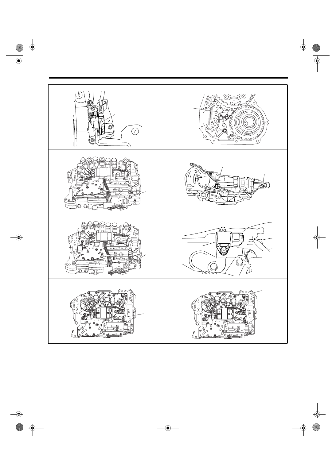
Electrical Component Location
(1)
AT-00375
AT-01447
(2)
AT-01445
(3)
(4)
(5)
AT-01448
AT-01446
(6)
(7)
AT-01475
AT-01759
(8)
AT-01760
(9)
5AT(diag)-12
AUTOMATIC TRANSMISSION (DIAGNOSTICS)
Electrical Component Location
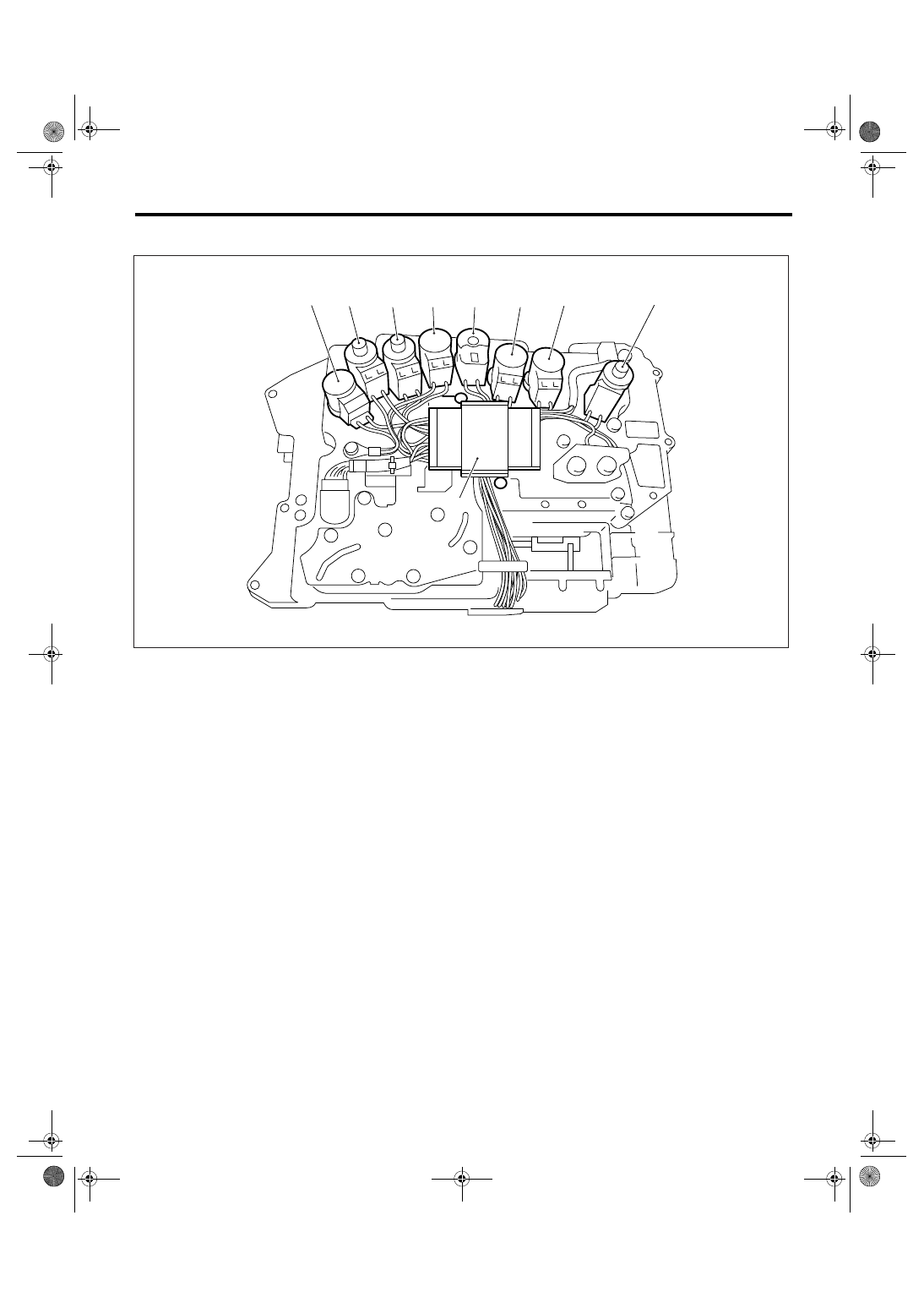
3. SOLENOID
(1)
High & low reverse clutch solenoid
(4)
Input clutch solenoid
(7)
Transfer solenoid
(2)
Direct clutch solenoid
(5)
Line pressure solenoid
(8)
Low coast brake solenoid
(3)
Front brake solenoid
(6)
Lock up solenoid
(9)
Memory box
AT-01449
(8)
(6)
(5)
(1)
(7)
(9)
(4)
(2)
(3)
5AT(diag)-13
AUTOMATIC TRANSMISSION (DIAGNOSTICS)
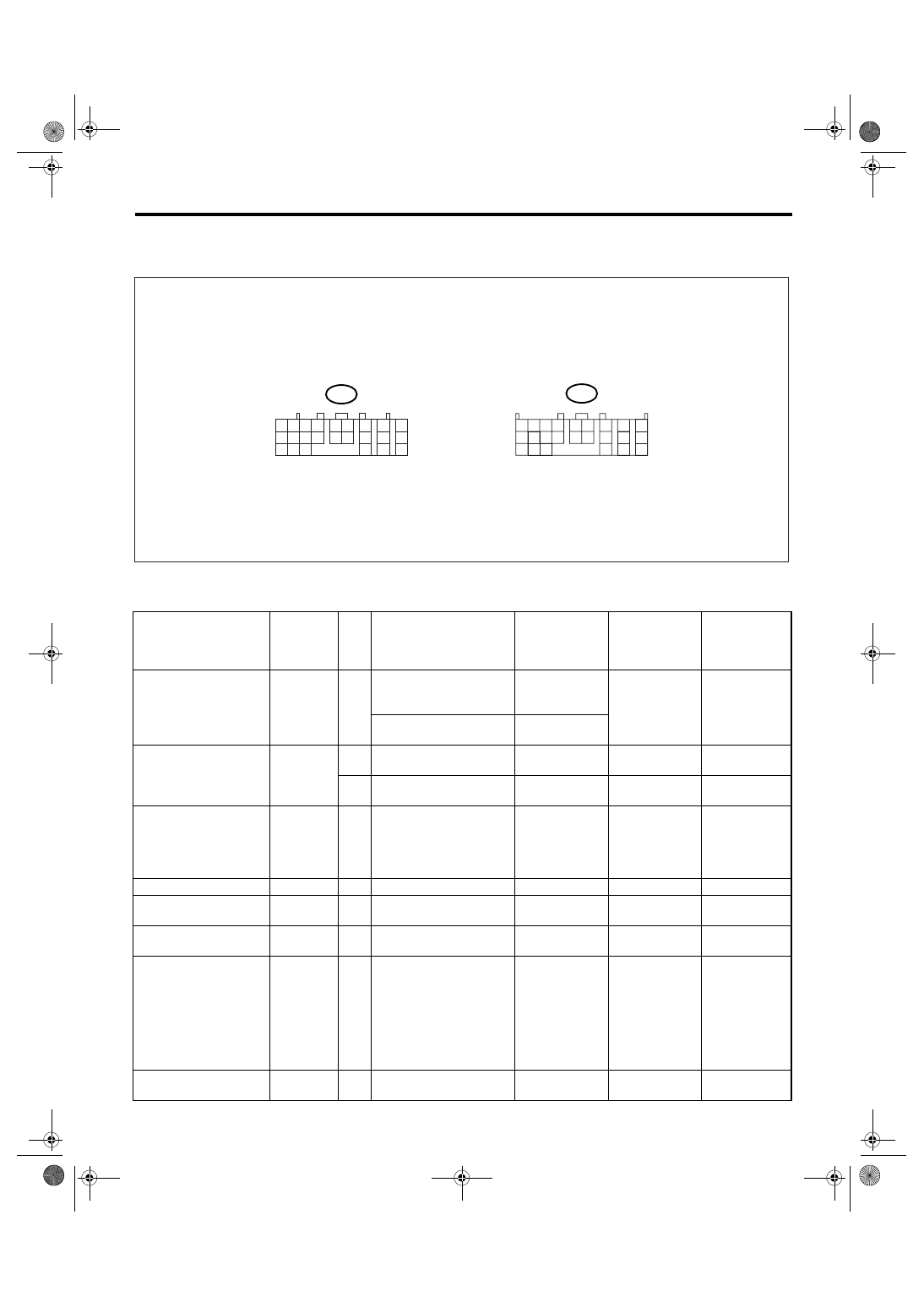
Transmission Control Module (TCM) I/O Signal
5. Transmission Control Module (TCM) I/O Signal
A: ELECTRICAL SPECIFICATION
NOTE:
The measurement should be performed after warming up.
Item
Connector
No.
Ter-
min
al
No.
Measuring conditions
Voltage (V)
Resistance
between termi-
nal and chassis
ground
Remarks
P/L solenoid output
B54
9
Engine ON, “P” range,
Accelerator OFF, Brake
ON
Approx. 4.0 —
6.0 V
3 — 9
Ω (ATF
temperature
20
°C (68°F))
Driving fre-
quency 750 —
850 Hz
Manual mode 1st, Accel-
erator OFF, Brake ON
Approx. 2.0 —
4.0 V
PVIGN power supply
B54
8
Ignition switch ON
Power supply
voltage
—
7
Ignition switch ON
Power supply
voltage
—
I/C oil pressure switch
input
B54
6
—
—
—
The condition
of I/C oil pres-
sure switch
cannot read by
the tester.
Power GND
B54
5
Always
Approx. 0 V
—
CAN communication line
(+)
B54
4
—
—
—
CAN communication line
(
−)
B54
3
—
—
—
ATF temperature sensor
1 input
B54
2
Ignition switch ON
2.5 — 2.9 V
(ATF tempera-
ture 20
°C
(68
°F))
0.8 — 1.0 V
(ATF tempera-
ture 80
°C
(176
°F))
4.0 — 5.0 k
Ω
(ATF tempera-
ture 20
°C
(68
°F))
0.7 — 0.9 k
Ω
(ATF tempera-
ture 80
°C
(176
°F))
Battery power supply
B54
1
Always
Power supply
voltage
—
AT-01451
1 2 3 4
10 11 12
19 20 21
13
5 6
14 15
7
8
9
16
17
18
22
23
24
1 2
7
8
9
5 6
3 4
10 11 12
19 20 21
13
14 15
16
17
18
22
23
24
B55
B54

5AT(diag)-14
AUTOMATIC TRANSMISSION (DIAGNOSTICS)
Transmission Control Module (TCM) I/O Signal
I/C solenoid output
B54
18
While driving at 1st — 3rd
of manual mode
Approx. 5.5 —
7.5 V
3 — 9
Ω (ATF
temperature
20
°C (68°F))
Driving fre-
quency 750 —
850 Hz
While driving at 4th or 5th
of manual mode
Approx. 0 V
H&LR/C solenoid output
B54
17
While driving at 2nd of
manual mode
Approx. 5.5 —
7.5 V
3 — 9
Ω (ATF
temperature
20
°C (68°F))
Driving fre-
quency 750 —
850 Hz
While driving at 3rd — 5th
of manual mode
Approx. 0 V
Control valve power sup-
ply output
B54
16
Ignition switch ON
Power supply
voltage
—
Ignition switch OFF
Approx. 0 V
LC/B solenoid output
B54
15
While driving at 1st — 2nd
of manual mode
Power supply
voltage
5 — 17
Ω (ATF
temperature
25
°C (77°F))
While driving at 3rd — 5th
of manual mode
Approx. 0 V
Power GND
B54
14
Always
Approx. 0 V
—
Analog GND (Sensor
GND)
B54
13
Always
Approx. 0 V
—
LC/B oil pressure switch
input
B54
12
—
—
—
The condition
of LC/B oil
pressure switch
cannot read by
the tester.
ATF temperature sensor
2 input
B54
11
Ignition switch ON
2.3 — 2.7 V
(ATF tempera-
ture 20
°C
(68
°F))
0.6 — 0.8 V
(ATF tempera-
ture 80
°C
(176
°F))
3.0 — 3.6 k
Ω
(ATF tempera-
ture 20
°C
(68
°F))
0.4 — 0.6 k
Ω
(ATF tempera-
ture 80
°C
(176
°F))
PVIGN power supply
relay output
B54
10
Ignition switch ON
0 — 1.5 V
—
Fr/B solenoid output
B54
24
While driving at other than
4th of manual mode
Approx. 4.5 —
6.5 V
3 — 9
Ω (ATF
temperature
20
°C (68°F))
Driving fre-
quency 750 —
850 Hz
While driving at 4th of
manual mode
Approx. 0 V
L/U solenoid output
B54
23
When lock-up
Approx. 3.5 —
5.5 V
3 — 9
Ω (ATF
temperature
20
°C (68°F))
Driving fre-
quency 750 —
850 Hz
When not lock-up
Approx. 0 V
D/C solenoid output
B54
22
While driving at 1st or 5th
of manual mode
Approx. 5.5 —
7.5 V
3 — 9
Ω (ATF
temperature
20
°C (68°F))
Driving fre-
quency 750 —
850 Hz
While driving at 2nd — 4th
of manual mode
Approx. 0 V
D/C oil pressure switch
input
B54
21
—
—
—
The condition
of D/C oil pres-
sure switch
cannot read by
the tester.
Subaru Select Monitor
communication line
B54
20
—
—
—
Control GND
B54
19
Always
Approx. 0 V
—
Item
Connector
No.
Ter-
min
al
No.
Measuring conditions
Voltage (V)
Resistance
between termi-
nal and chassis
ground
Remarks
Нет комментариевНе стесняйтесь поделиться с нами вашим ценным мнением.
Текст