Subaru Legacy (2005 year). Service manual — part 84
CO(H4SO 2.0)-11
COOLING
Radiator Fan System
22
CHECK HARNESS BETWEEN MAIN FAN
RELAY 1 TERMINAL AND MAIN FAN MO-
TOR CONNECTOR.
1) Disconnect the connector from main fan
motor.
2) Measure the resistance of harness
between main fan relay 1 terminal and main
fan motor connector.
Connector & terminal
(F17) No. 2 — (F36) No. 6:
Is the resistance less than 1
Ω?
Repair the open
circuit of harness
between main fan
relay 1 terminal
and main fan
motor connector.
23
CHECK HARNESS BETWEEN MAIN FAN
RELAY 1 AND ECM.
1) Disconnect the connector from ECM.
2) Measure the resistance between main fan
relay 1 terminal and ECM connector.
Connector & terminal
2.5 L EC, EK, K4, EH, ER model
(B135) No. 34 — (B143) No. 7:
Except for 2.5 L EC, EK, K4, EH, ER model
(B134) No. 9 — (B143) No. 7:
Is the resistance less than 1
Ω?
Repair the open
circuit of harness
between main fan
relay 1 terminal
and ECM.
24
CHECK HARNESS BETWEEN MAIN FAN
RELAY 2 AND ECM.
Measure the resistance between main fan
relay 2 terminal and ECM connector.
Connector & terminal
2.5 L EC, EK, K4, EH, ER model
(B135) No. 34 — (F27) No. 3:
Except for 2.5 L EC, EK, K4, EH, ER model
(B134) No. 9 — (F27) No. 3:
Is the resistance less than 1
Ω?
Repair the open
circuit of harness
between main fan
relay 2 terminal
and ECM.
25
CHECK FUSE.
1) Turn the ignition switch to OFF.
2) Remove the fuse No. 4 and No. 26.
3) Check the condition of fuse.
Is the fuse blown out?
Replace the fuse.
26
CHECK POOR CONTACT.
Check poor contact in ECM connector.
Is there a poor contact in ECM
connector?
Repair the poor
contact in ECM
connector.
Repair the power
supply circuit for
main fuse box.
27
CHECK OPERATION OF RADIATOR FAN.
Check if the sub fan rotates when both fans do
not rotate at high speed under the step 2.
Does the sub fan rotate?
28
CHECK GROUND CIRCUIT OF MAIN FAN
RELAY 2.
1) Remove the main fan relay 2 from A/C relay
holder.
2) Measure the resistance between main fan
relay 2 terminal and chassis ground.
Connector & terminal
(F27) No. 4 — Chassis ground:
Is the resistance less than 1
Ω?
Repair the open
circuit of harness
between main fan
relay 2 and chas-
sis ground.
29
CHECK POWER SUPPLY TO MAIN FAN RE-
LAY 2.
1) Turn the ignition switch to ON.
2) Measure the voltage between main fan
relay 2 terminal and chassis ground.
Connector & terminal
(F27) No. 1 (+) — Chassis ground (
−
):
Is the voltage more than 10 V? Go to step 30.
Repair the power
supply line.
Step
Check
Yes
No
CO(H4SO 2.0)-12
COOLING
Radiator Fan System
30
CHECK MAIN FAN RELAY 2.
1) Turn the ignition switch to OFF.
2) Remove the main fan relay 2.
3) Measure the resistance of main fan relay 2.
Terminal
(F27) No. 2 — (F27) No. 4:
Is the resistance more than 1
M
Ω?
Replace the main
fan relay 2.
31
CHECK MAIN FAN RELAY 2.
1) Connect the battery to terminals No. 1 and
No. 3 of main fan relay 2.
2) Measure the resistance of main fan relay 2.
Terminal
(F27) No. 4 — (F27) No. 5:
Is the resistance less than 1
Ω?
Replace the main
fan relay 2.
Step
Check
Yes
No
CO(H4SO 2.0)-13
COOLING
Engine Coolant
3. Engine Coolant
A: REPLACEMENT
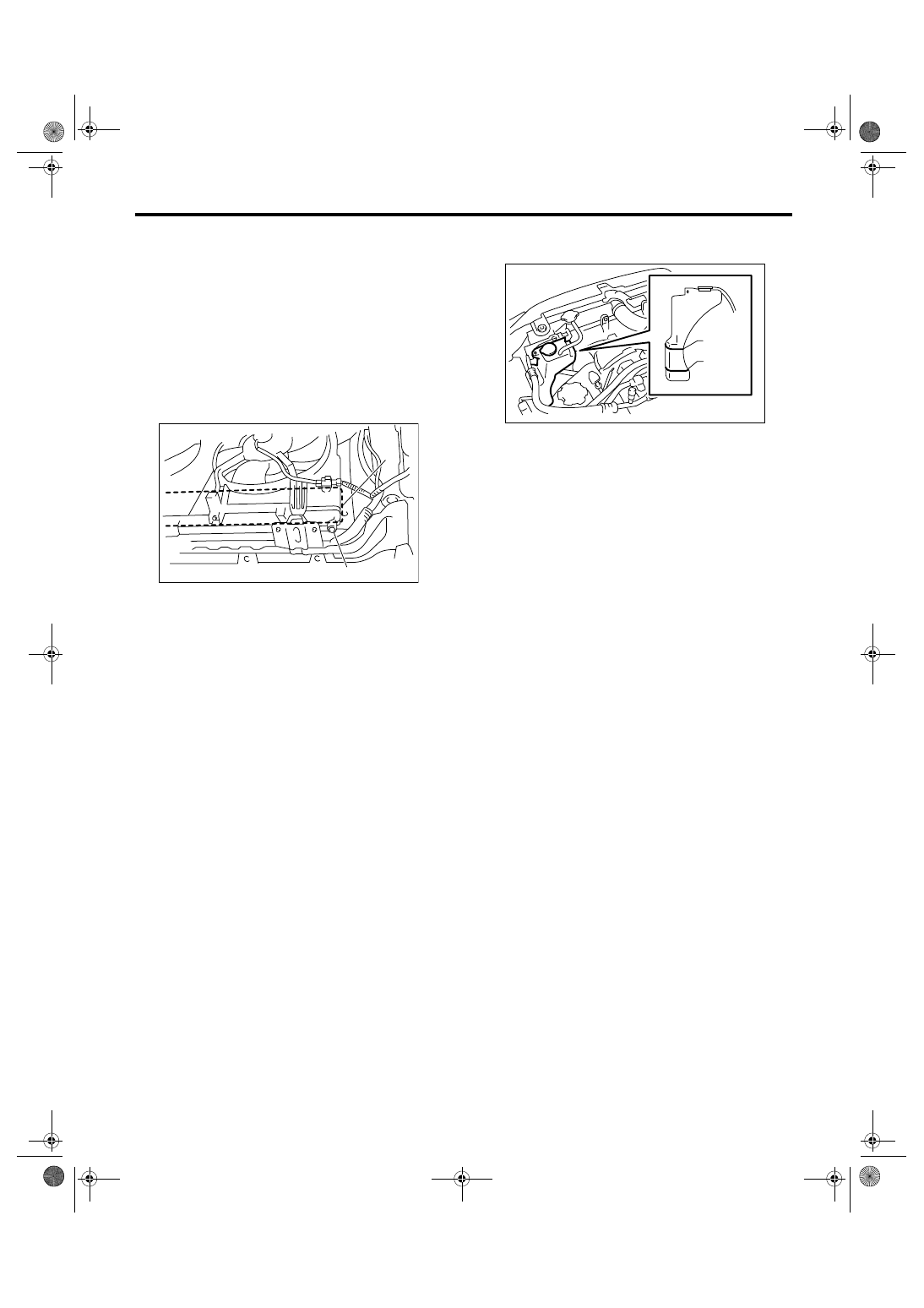
1. DRAINING OF ENGINE COOLANT
1) Lift-up the vehicle.
2) Remove the under cover.
3) Remove the drain plug to drain engine coolant
into container.
NOTE:
Remove the radiator cap so that engine coolant will
drain faster.
4) Install the drain plug.
2. FILLING OF ENGINE COOLANT
1) Fill engine coolant into the radiator up to the filler
neck position.
Engine coolant capacity (fill up to “FULL” level):
LHD
MT model
6.4
2(6.8 US qt, 5.6 Imp qt)
AT model (Model without ATF warmer)
6.3
2(6.7 US qt, 5.5 Imp qt)
AT model (Model with ATF warmer)
6.7
2(7.0 US qt, 5.9 Imp qt)
RHD
MT model
6.5
2(6.9 US qt, 5.7 Imp qt)
AT model (Model without ATF warmer)
6.4
2(6.8 US qt, 5.6 Imp qt)
AT model (Model with ATF warmer)
6.8
2(7.2 US qt, 6.0 Imp qt)
NOTE:
The SUBARU genuine coolant containing anti-
freeze and anti-rust agents is especially made for
SUBARU engine, which has an aluminum crank-
case. Always use SUBARU genuine coolant, since
other coolant may cause corrosion.
2) Fill engine coolant into the reservoir tank up to
“FULL” level.
3) Close the radiator cap and start the engine.
Race 5 to 6 times at less than 3,000 rpm, then stop
the engine. (Complete this operation within 40 sec-
onds.)
4) Wait for one minute after the engine stops, open
the radiator cap. If the engine coolant level drops,
add engine coolant into radiator up to the filler neck
position.
5) Perform the procedures 3) and 4) again.
6) Attach the radiator cap and reservoir tank cap
properly.
7) Start the engine and operate the heater at max-
imum hot position and the blower speed setting to
“LO”.
8) Run the engine at 2,000 rpm or less until ratiator
fan starts and stops.
NOTE:
• Be careful with the engine coolant temperature
gauge to prevent overheating.
• If the radiator hose becomes to harden by the
pressure of engine coolant, air bleeding operation
seems to be almost completed.
9) Stop the engine and wait until engine coolant
temperature lowers to 30
°C (86°F).
10) Open the radiator cap. If the engine coolant lev-
el drops, add engine coolant into radiator up to the
filler neck position and reservoir tank to “FULL” lev-
el.
11) Attach the radiator cap and reservoir tank cap
properly.
12) Operate the heater at maximum hot position
and the blower speed setting to “LO” and start the
engine. Race at less than 3,000 rpm. If the flowing
sound is heard at this time, perform the procedures
from 8) again.
(A) Drain plug
(B) Heat shield cover
CO-00268
(A)
(B)
CO-00269
FULL
FULL
LOW
LOW
CO(H4SO 2.0)-14
COOLING
Engine Coolant
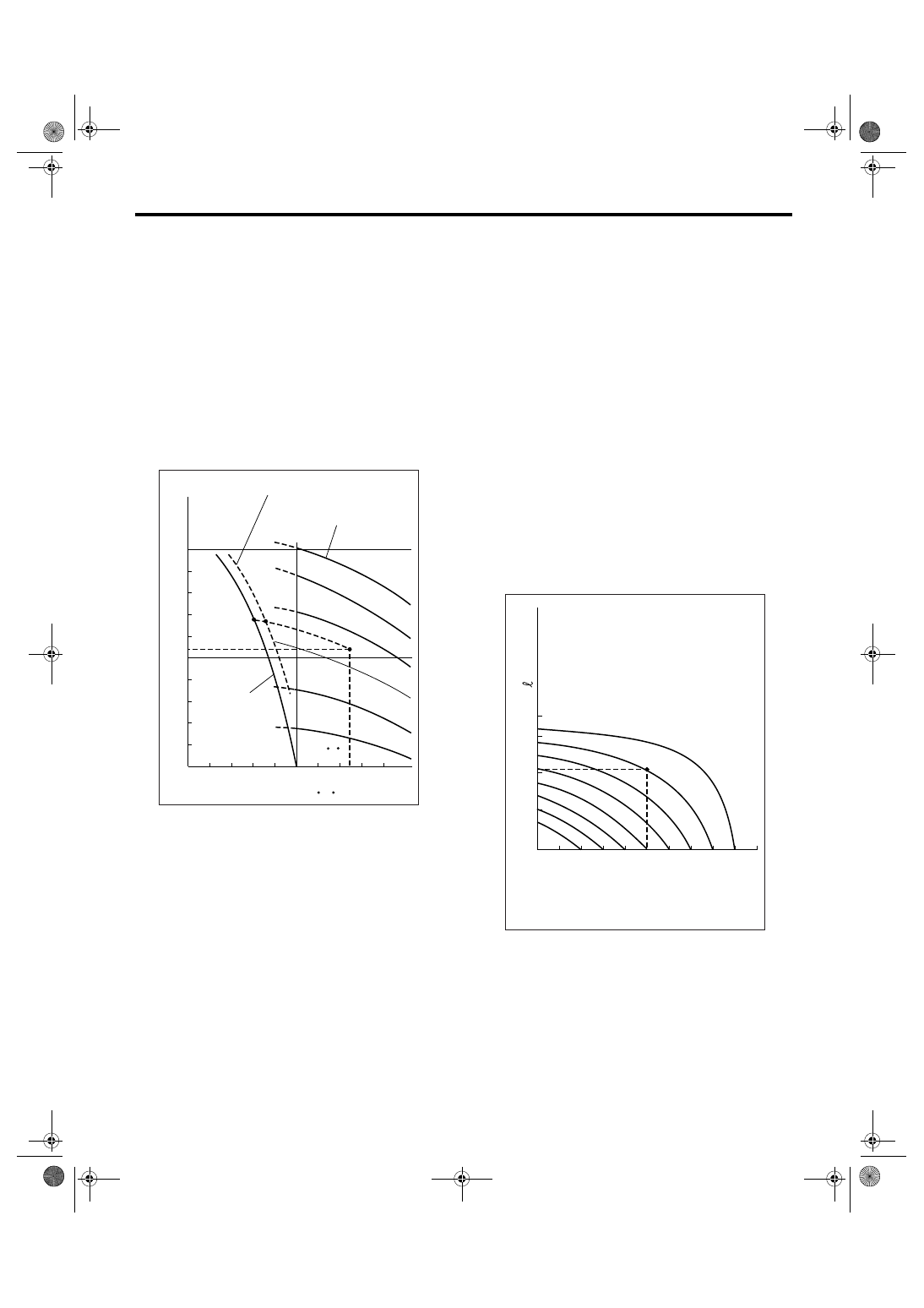
B: INSPECTION
1. RELATIONSHIP OF SUBARU COOLANT
CONCENTRATION AND FREEZING TEM-
PERTAURE
The concentration and safe operating temperature
of SUBARU coolant is shown in the diagram. Mea-
suring the temperature and specific gravity of the
coolant will provide this information.
[Example]
If the coolant temperature is 25
°C (77°F), its specif-
ic gravity is 1.054 and the concentration is 35%
(point A), the safe operating temperature is
−14°C
(7
°F) (point B), and the freezing temperature is −
20
°C (−4°F) (point C).
2. PROCEDURE TO ADJUST THE CON-
CENTRATION OF THE COOLANT
To adjust the concentration of coolant according to
temperature, find the proper fluid concentration in
the above diagram and replace the necessary
amount of coolant with an undiluted solution of
SUBARU genuine coolant (concentration 50%).
The amount of coolant that should be replaced can
be determined using the diagram.
[Example]
Assume that the coolant concentration must be in-
creased from 25% to 40%. Find point A, where the
25% line of coolant concentration intersects with
the 40% curve of the necessary coolant concentra-
tion, and read the scale on the vertical axis of the
graph at height A. The quantity of coolant to be
drained is 2.1
2(2.2 US qt, 1.8 Imp qt). Drain 2.1
2(2.2 US qt, 1.8 Imp qt) of coolant from the cooling
system and add 2.1
2(2.2 US qt, 1.8 Imp qt) of the
undiluted solution of SUBARU coolant.
If a coolant concentration of 50% is needed, drain
all the coolant and refill with the undiluted solution
only.
CO-02172
60%
(1.054)
1.000
1.010
1.020
1.030
1.040
1.050
1.060
1.070
1.080
1.090
1.100
Safe operating temperature
Freezing
temperature
Concentration
of coolant
Specific gravity
of coolant
Coolant temperature
B
A
C
-40
(-40) (-22) (-4) (14) (32) (50) (68) (86)
( F)
(104)
-30
-20 -10
0
10
20
30
40
(77 F)
50%
40%
30%
20%
25 C
10%
C
CO-00012
10
0
1
2
3
(1.1,
0.9)
(2.1,
1.8)
(3.2,
2.6)
10% 15%
25%
20%
30%
35%
40%
45%
A
20
30
40
50
Concentration of coolant in vehicie
and quantity to be drained
Quantity of coolant to be
drained (US qt, Imp qt)
Necessary Concentration
of coolant
Concentration of coolant in
the vehicie cooling system %
Нет комментариевНе стесняйтесь поделиться с нами вашим ценным мнением.
Текст