Subaru Legacy (2005 year). Service manual — part 83
CO(H4SO 2.0)-7
COOLING
Radiator Fan System
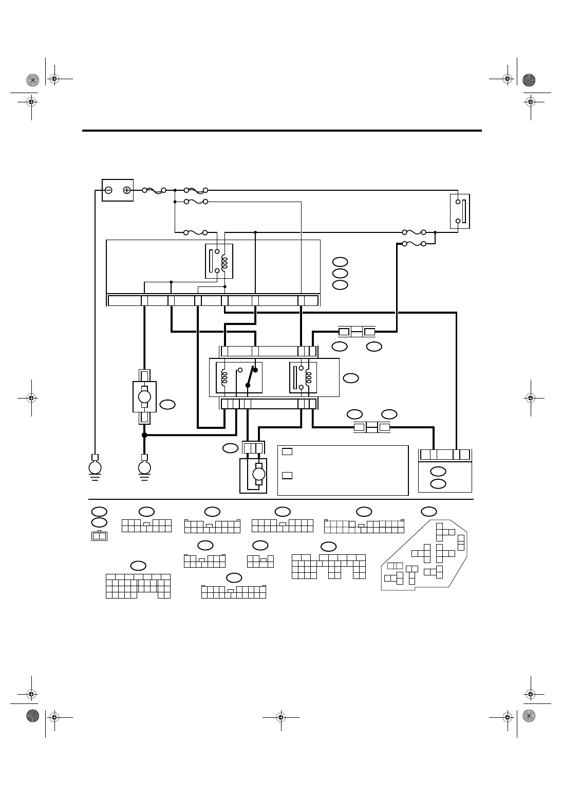
2. Radiator Fan System
A: WIRING DIAGRAM
CO-02166
B135
F108
F16
B361
F17
F16
2 1
1
7
B360
1 2 3
4 5 6 7
8 9 10 11 12 13 14 15 16
F108
2 3
8
10
1
9
4
11 12 13 14 15 16
5 6 7
17 18
F27
13
14
15
16 17
27
24 25
26
20 21
22
23
29
30
31
28
8 9
10
11
12
1
2
5
3
4
7
6
19
18
B135
F36
F35
B143
5
6
7
2
1
3
4
29
10 11 12 13 14 15
25
24
16
30
9
8
17 18 19
20
28
21 22 23
32
31
26 27
33
34 35
F17
B361
1
7
2 3
4 5 6
8 9 10 11 12 13 14
F109
3 4
1 2
8 9 10 11
12 13 14 15 16 17 18 19 20 21 22 23 24
5
6 7
F27
1 2 3 4
5 6 7 8 9
10 11 12 13 14 15 16 17 18 19 20
1 2
3 4 5
6 7 8 9 10 11 12
3
1 2
7
4 5
6
16
7
1
2
3
4
5
21
22
E6
E5
C10
B7
C11
E3
1
2
20
23
E
E
M
2
1
M
F109
B360
10
1
SBF-6
MAIN SBF
No.3
No.22
No.26
B143
B:
F35
C:
F36
E:
1
2
B:
C:
E:
ECM
IGNITION
SWITCH
MAIN FUSE BOX (M/B)
MAIN
FAN
RELAY 1
MAIN
FAN
RELAY 2
SUB
FAN
RELAY
A/C RELAY HOLDER
THROUGH JOINT
CONNECTOR
THROUGH JOINT
CONNECTOR
MAIN FAN
MOTOR
SUB FAN
MOTOR
B134
5
6
7
8
2
1
9
4
3
10
24
22 23
25
11 12 13 14 15
26 27
28
16 17
18 19 20 21
33 34
29
32
30 31
A:
B134
A:
B:
*
*
1
*
2
*
2.5 L
EC, EK, K4, EH, ER,
MODEL: A31
EXCEPT FOR 2.5 L
EC, EK, K4, EH, ER
MODEL: A10
2.5 L
EC, EK, K4, EH, ER,
MODEL: B34
EXCEPT FOR 2.5 L
EC, EK, K4, EH, ER
MODEL: A9
B:
No.4
CO(H4SO 2.0)-8
COOLING
Radiator Fan System
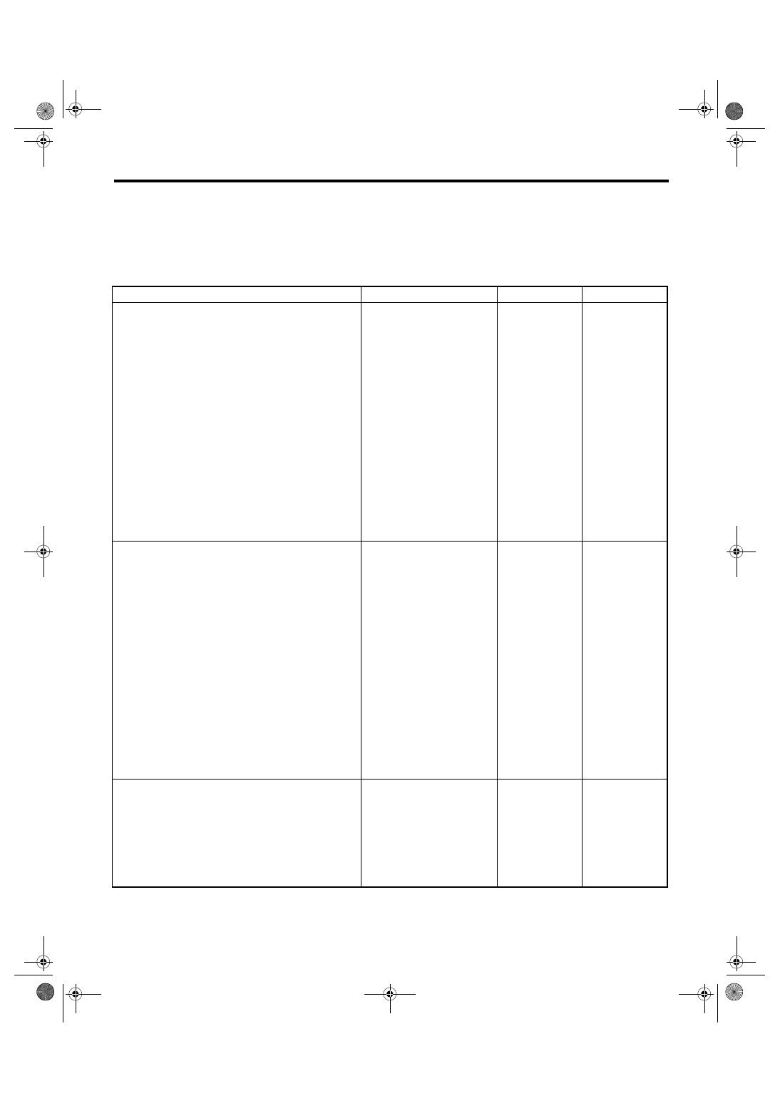
B: INSPECTION
DETECTING CONDITION:
• Engine coolant temperature is more than 96
°C (205°F).
• Vehicle speed is below 19 km/h (12 MPH).
TROUBLE SYMPTOMS:
Radiator main and sub fan do not rotate under the above conditions.
Step
Check
Yes
No
1
CHECK OPERATION OF RADIATOR FAN.
1) Connect the test mode connector.
2) Turn the ignition switch to ON.
3) Perform the compulsory operation check for
the radiator fan relay using Subaru Select
Monitor.
NOTE:
• When performing the compulsory operation
check for the radiator fan relay using Subaru
Select Monitor, the radiator main fan and sub
fan will repeat such a operation as low speed
revolution
→ high speed revolution → OFF in
this order.
• Subaru Select Monitor
Refer to Compulsory Valve Operation Check
Mode for more operation procedure. <Ref. to
EN(H4SO 2.0)(diag)-39, Compulsory Valve
Operation Check Mode.> or <Ref. to EN(H4SO
2.5)(diag)-41, Compulsory Valve Operation
Check Mode.>
Do the radiator main fan and
sub fan rotate at low speed?
2
CHECK OPERATION OF RADIATOR FAN.
1) Connect the test mode connector.
2) Turn the ignition switch to ON.
3) Perform the compulsory operation check for
the radiator fan relay using Subaru Select
Monitor.
NOTE:
• When performing the compulsory operation
check for the radiator fan relay using Subaru
Select Monitor, the radiator main fan and sub
fan will repeat such a operation as low speed
revolution
→ high speed revolution → OFF in
this order.
• Subaru Select Monitor
Refer to Compulsory Valve Operation Check
Mode for more operation procedure. <Ref. to
EN(H4SO 2.0)(diag)-39, Compulsory Valve
Operation Check Mode.> or <Ref. to EN(H4SO
2.5)(diag)-41, Compulsory Valve Operation
Check Mode.>
Do the radiator main fan and
sub fan rotate at high speed?
Radiator fan sys-
tem is normal.
3
CHECK POWER SUPPLY TO SUB FAN RE-
LAY.
1) Turn the ignition switch to OFF.
2) Remove the sub fan relay from A/C relay
holder.
3) Measure the voltage between sub fan relay
terminal and chassis ground.
Connector & terminal
(F27) No. 20 (+) — Chassis ground (
−
):
Is the voltage more than 10 V? Go to step 4.
CO(H4SO 2.0)-9
COOLING
Radiator Fan System
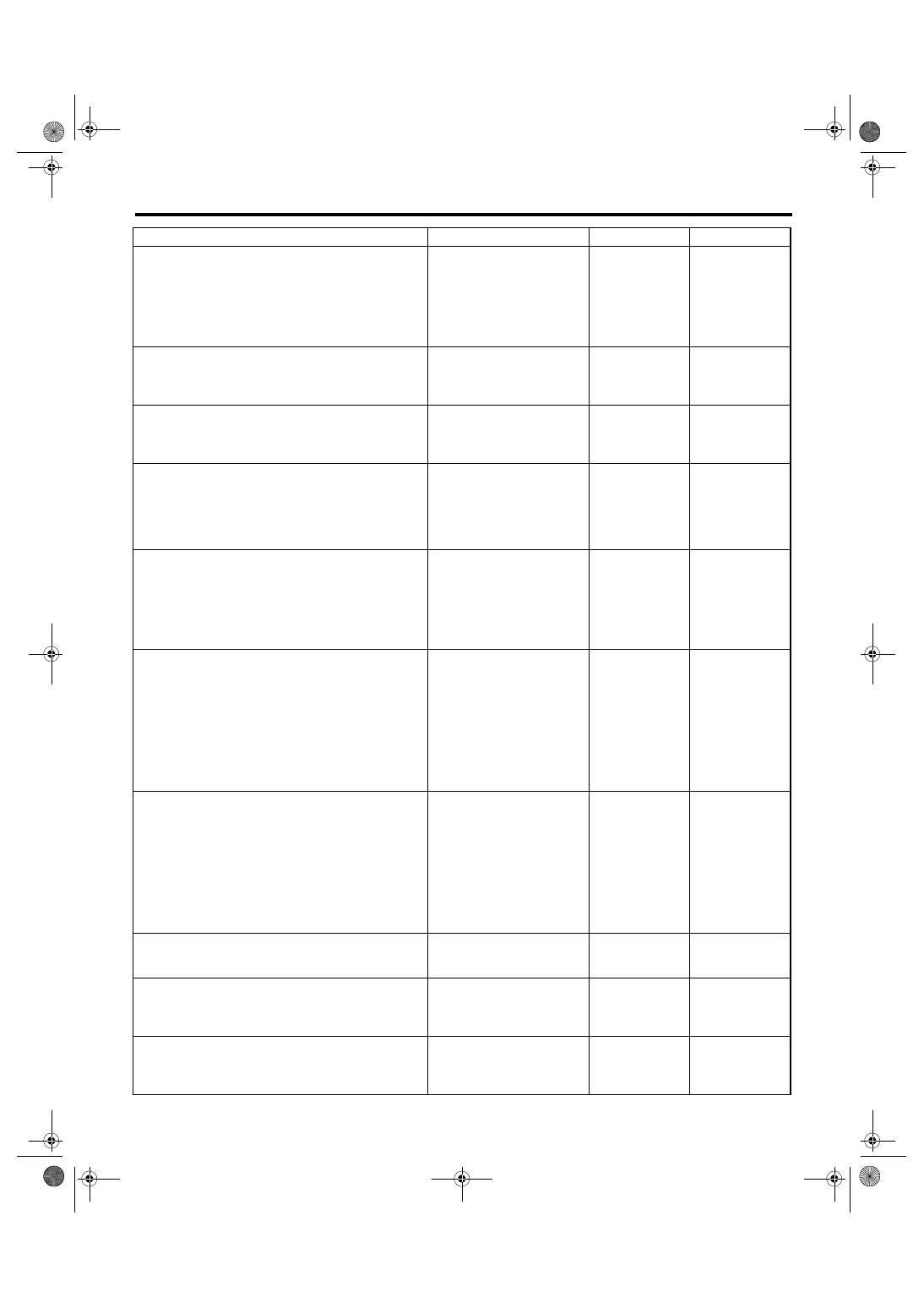
4
CHECK POWER SUPPLY TO SUB FAN RE-
LAY.
1) Turn the ignition switch to ON.
2) Measure the voltage between sub fan relay
terminal and chassis ground.
Connector & terminal
(F27) No. 23 (+) — Chassis ground (
−
):
Is the voltage more than 10 V? Go to step 7.
5
CHECK FUSE.
1) Turn the ignition switch to OFF.
2) Remove the fuse No. 3.
3) Check the condition of fuse.
Is the fuse blown out?
Replace the fuse.
Repair the power
supply line.
6
CHECK FUSE.
1) Turn the ignition switch to OFF.
2) Remove the fuse No. 22.
3) Check the condition of fuse.
Is the fuse blown out?
Replace the fuse.
Repair the power
supply line.
7
CHECK SUB FAN RELAY.
1) Turn the ignition switch to OFF.
2) Measure the resistance between sub fan
relay terminals.
Terminal
No. 20 — No. 21:
Is the resistance more than 1
M
Ω?
Replace the sub
fan relay.
8
CHECK SUB FAN RELAY.
1) Connect the terminals No. 22 and No. 23 of
sub fan relay to battery.
2) Measure the resistance between sub fan
relay terminals.
Terminal
No. 20 — No. 21:
Is the resistance less than 1
Ω?
Replace the sub
fan relay.
9
CHECK HARNESS BETWEEN SUB FAN RE-
LAY TERMINAL AND SUB FAN MOTOR
CONNECTOR.
1) Disconnect the connector from sub fan
motor.
2) Measure the resistance of harness
between sub fan relay terminal and sub fan
motor connector.
Connector & terminal
(F16) No. 2 — (F27) No. 21:
Is the resistance less than 1
Ω?
Repair the open
circuit of harness
between sub fan
relay terminal and
sub fan motor con-
nector.
10
CHECK HARNESS BETWEEN SUB FAN MO-
TOR CONNECTOR AND MAIN FAN RELAY 2
CONNECTOR.
1) Remove the main fan relay 2 from A/C relay
holder.
2) Measure the resistance of harness
between sub fan motor connector and main fan
relay 2 connector.
Connector & terminal
(F16) No. 1 — (F27) No. 5:
Is the resistance less than 1
Ω?
Repair the open
circuit of harness
between sub fan
motor connector
and main fan relay
2 connector.
11
CHECK POOR CONTACT.
Check the poor contact in sub fan motor con-
nector.
Is there poor contact in sub fan
motor connector?
Repair the poor
contact in sub fan
motor connector.
12
CHECK SUB FAN MOTOR.
Connect the battery positive (+) terminal to
terminal No. 2 of sub fan motor, and the
ground (
−) terminal to terminal No. 1.
Does the sub fan rotate?
Replace the sub
fan motor.
13
CHECK MAIN FAN RELAY 2.
Measure the resistance of main fan relay 2.
Terminal
No. 2 — No. 5:
Is the resistance less than 1
Ω?
Replace the main
fan relay 2.
Step
Check
Yes
No
CO(H4SO 2.0)-10
COOLING
Radiator Fan System
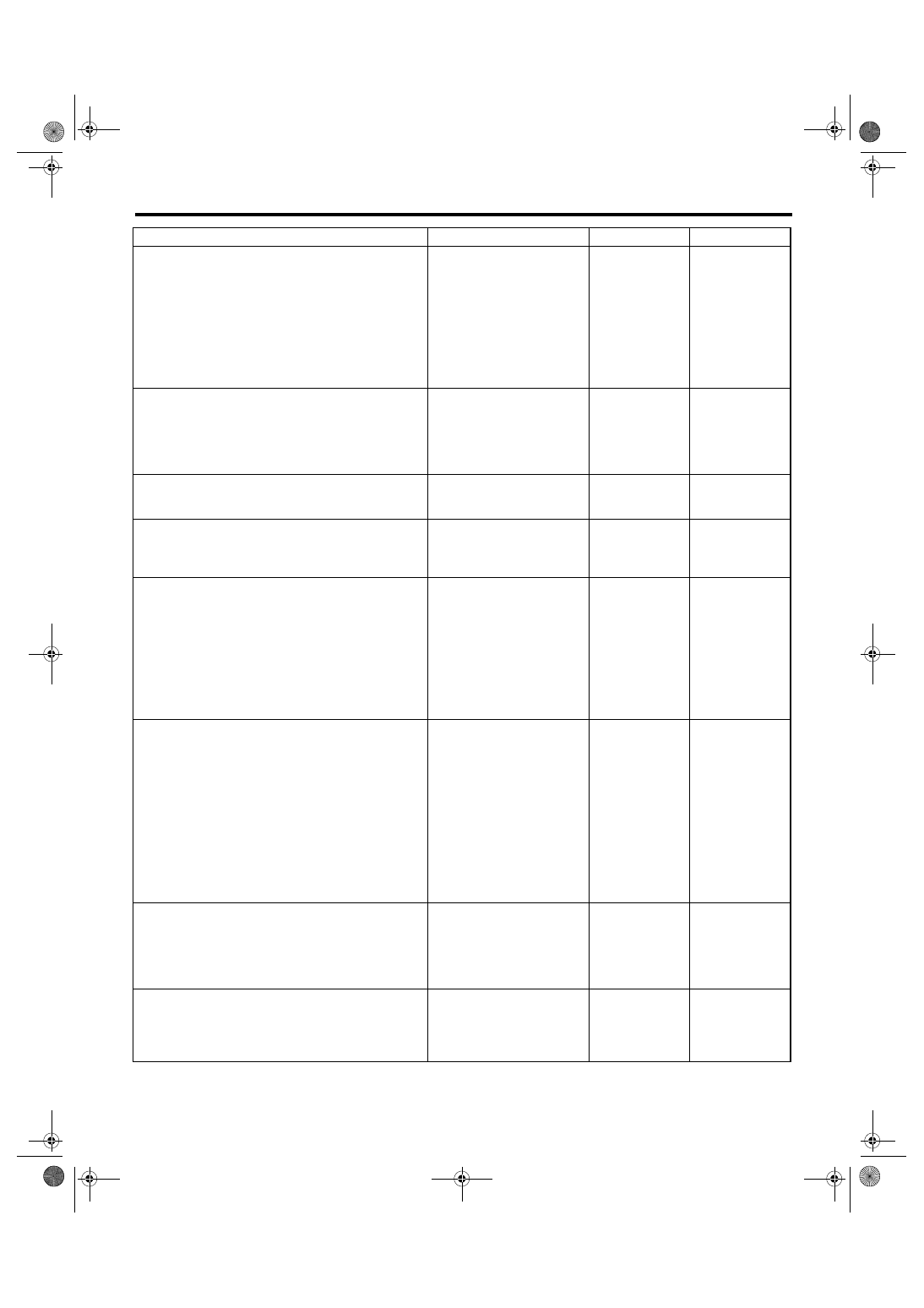
14
CHECK HARNESS BETWEEN MAIN FAN
RELAY 2 TERMINAL AND MAIN FAN MO-
TOR CONNECTOR.
1) Disconnect the connector from main fan
motor.
2) Measure the resistance of harness
between main fan relay 2 terminal and main
fan motor connector.
Connector & terminal
(F17) No. 2 — (F27) No. 2:
Is the resistance less than 1
Ω?
Repair the open
circuit of harness
between main fan
relay 2 terminal
and main fan
motor connector.
15
CHECK MAIN FAN MOTOR AND GROUND
CIRCUIT.
Measure the resistance between main fan
motor connector and chassis ground.
Connector & terminal
(F17) No. 1 — Chassis ground:
Is the resistance less than 5
Ω?
Repair the open
circuit of harness
between main fan
motor connector
and chassis
ground.
16
CHECK POOR CONTACT.
Check poor contact in main fan motor connec-
tor.
Is there poor contact in main
fan motor connector?
Repair the poor
contact in main fan
motor connector.
17
CHECK MAIN FAN MOTOR.
Connect the battery positive (+) terminal to ter-
minal No. 2 of main fan motor, and the ground
(
−) terminal to terminal No. 1.
Does the main fan rotate?
Replace the main
fan motor.
18
CHECK HARNESS BETWEEN SUB FAN RE-
LAY AND ECM.
1) Disconnect the connector from ECM.
2) Measure the resistance between sub fan
relay terminal and ECM connector.
Connector & terminal
2.5 L EC, EK, K4, EH, ER model
(B134) No. 31 — (F27) No. 22:
Except for 2.5 L EC, EK, K4, EH, ER model
(B134) No. 10 — (F27) No. 22:
Is the resistance less than 1
Ω?
Repair the open
circuit of harness
between sub fan
relay terminal and
ECM.
19
CHECK POOR CONTACT.
Check poor contact in ECM connector.
Is there a poor contact in ECM
connector?
Repair the poor
contact in ECM
connector.
Check the DTC.
Repair the trouble
cause. <Ref. to
EN(H4SO
2.0)(diag)-31,
Read Diagnostic
Trouble Code
(DTC).> or <Ref.
to EN(H4SO
2.5)(diag)-32,
Read Diagnostic
Trouble Code
(DTC).>
20
CHECK MAIN FAN RELAY 1.
1) Turn the ignition switch to OFF.
2) Remove the main fan relay 1 from main
fuse box.
3) Measure the resistance of terminal in main
fan relay 1 switch.
Is the resistance more than 1
M
Ω?
Replace the main
fan relay 1.
21
CHECK MAIN FAN RELAY 1.
1) Connect the battery to terminal of main fan
relay 1 coil.
2) Measure the resistance between terminals
of main fan relay 1 switch.
Is the resistance less than 1
Ω?
Replace the main
fan relay 1.
Step
Check
Yes
No
Нет комментариевНе стесняйтесь поделиться с нами вашим ценным мнением.
Текст