Subaru Legacy (2005 year). Service manual — part 774
ABS(diag)-61
ABS (DIAGNOSTICS)
Diagnostic Procedure with Diagnostic Trouble Code (DTC)
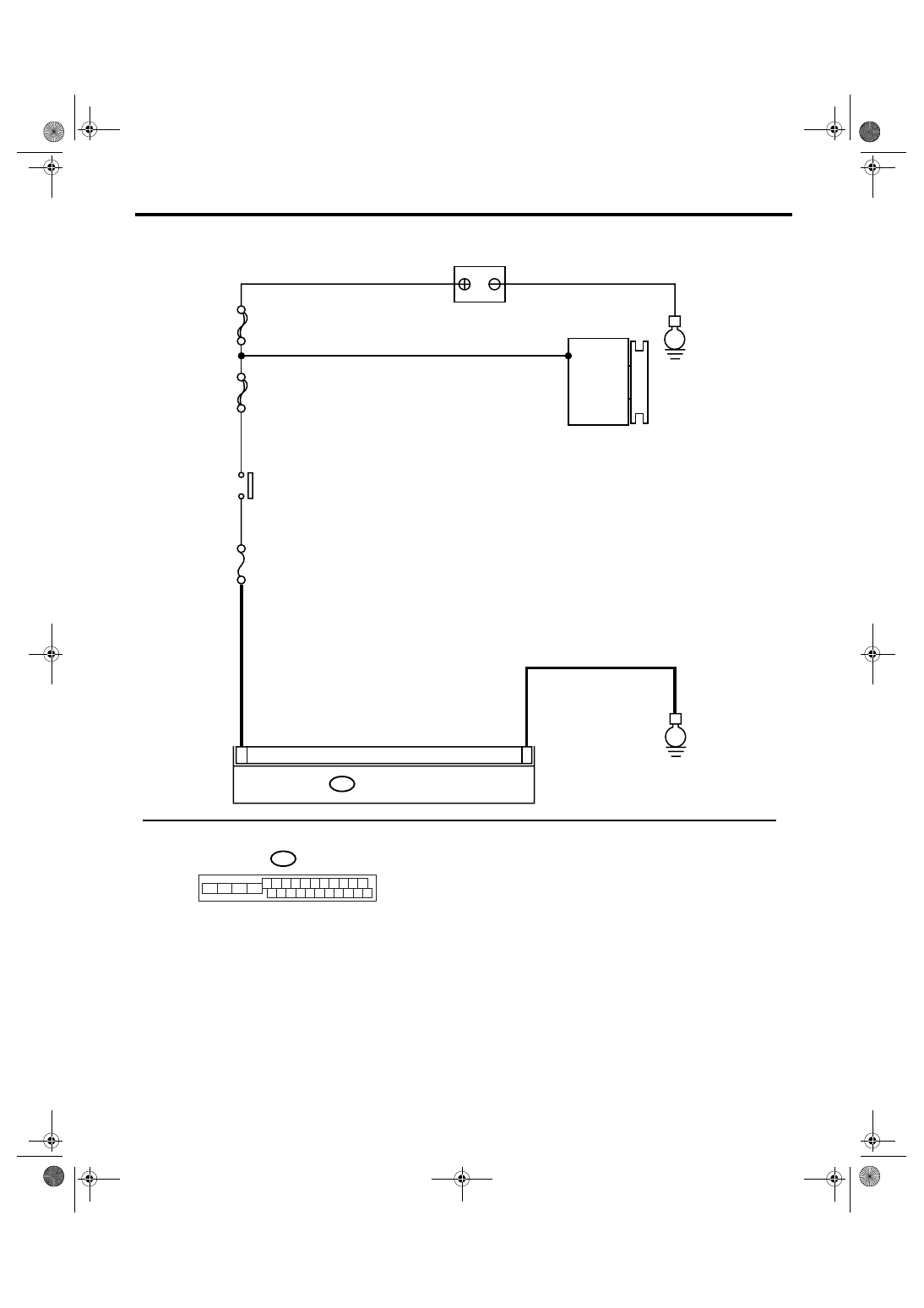
WIRING DIAGRAM:
ABS00622
MAIN SBF
SBF-6
No.33
B301
E
E
15
18
ABSCM & H/U
B301
1 2 3 4 5 6 7 8 9 10 11
16 17 18 19 20 21 22 23 24 25 26
13
12
15
14
BATTERY
IGNITION
SWITCH
GENERATOR
ABS(diag)-62
ABS (DIAGNOSTICS)
Diagnostic Procedure with Diagnostic Trouble Code (DTC)
Step
Check
Yes
No
1
CHECK GENERATOR.
1) Start the engine.
2) Run the engine at idle after warming up.
3) Measure the voltage between generator B
terminal and chassis ground.
Terminals
Generator B terminal (+) — Chassis
ground (
−
):
Is the voltage 10 — 15 V?
Repair the genera-
tor.
2
CHECK BATTERY TERMINAL.
Turn the ignition switch to OFF.
Are the positive and negative
battery terminals clamped
tightly?
Tighten the termi-
nal.
3
CHECK INPUT VOLTAGE OF ABSCM&H/U.
1) Disconnect the connector from ABSCM&H/
U.
2) Run the engine at idle.
3) Operate the devices such as headlights, air
conditioner, defogger, etc. which produce
much electrical loading.
4) Measure the voltage between ABSCM&H/
U connector and chassis ground.
Connector & terminal
(B301) No. 18 (+) — Chassis ground (
−
):
Is the voltage 10 — 15 V?
Repair the
ABSCM&H/U
power circuit.
4
CHECK GROUND CIRCUIT OF ABSCM&H/U.
1) Turn the ignition switch to OFF.
2) Measure the resistance between
ABSCM&H/U connector and chassis ground.
Connector & terminal
(B301) No. 15 — Chassis ground:
Is the resistance less than 0.5
Ω?
Repair the
ABSCM&H/U
ground harness.
5
CHECK POOR CONTACT IN CONNECTOR. Is there poor contact in con-
nector between generator, bat-
tery and ABSCM&H/U?
Repair the con-
nector.
6
CHECK ABSCM&H/U.
1) Connect all the connectors.
2) Perform clear memory mode.
3) Perform the inspection mode.
4) Read the DTC.
Is the same DTC displayed?
Replace the
ABSCM only.
<Ref. to ABS-8,
REPLACEMENT,
ABS Control Mod-
ule and Hydraulic
Control Unit
(ABSCM&H/U).>
7
CHECK ANY OTHER DTC ON DISPLAY.
Is any other DTC displayed?
Inspect the DTC
using “List of Diag-
nostic Trouble
Code (DTC)”.
<Ref. to
ABS(diag)-38, List
of Diagnostic Trou-
ble Code (DTC).>
Temporary poor
contact occurs.
ABS(diag)-63
ABS (DIAGNOSTICS)
Diagnostic Procedure with Diagnostic Trouble Code (DTC)
T: DTC C0140 CAN COMMUNICATION MALFUNCTION
DTC DETECTING CONDITION:
Defective CAN communication
TROUBLE SYMPTOM:
Possibly the vehicle speed cannot output on CAN.
Step
Check
Yes
No
1
CHECK LAN SYSTEM.
Perform the diagnosis for LAN system. <Ref. to
LAN(diag)-24, OPERATION, Read Diagnostic
Trouble Code (DTC).>
Is there any fault in LAN sys-
tem?
Repair it according
to DTC of LAN
system.
Replace the
ABSCM only.
<Ref. to ABS-8,
REPLACEMENT,
ABS Control Mod-
ule and Hydraulic
Control Unit
(ABSCM&H/U).>
ABS(diag)-64
ABS (DIAGNOSTICS)
Diagnostic Procedure with Diagnostic Trouble Code (DTC)
U: DTC C0114 VALVE RELAY MALFUNCTION
DTC DETECTING CONDITION:
Defective valve relay
TROUBLE SYMPTOM:
• ABS does not operate.
• EBD does not operate depending on the trouble contents.
NOTE:
Brake warning light comes on as well as ABS warning light when EBD does not operate.
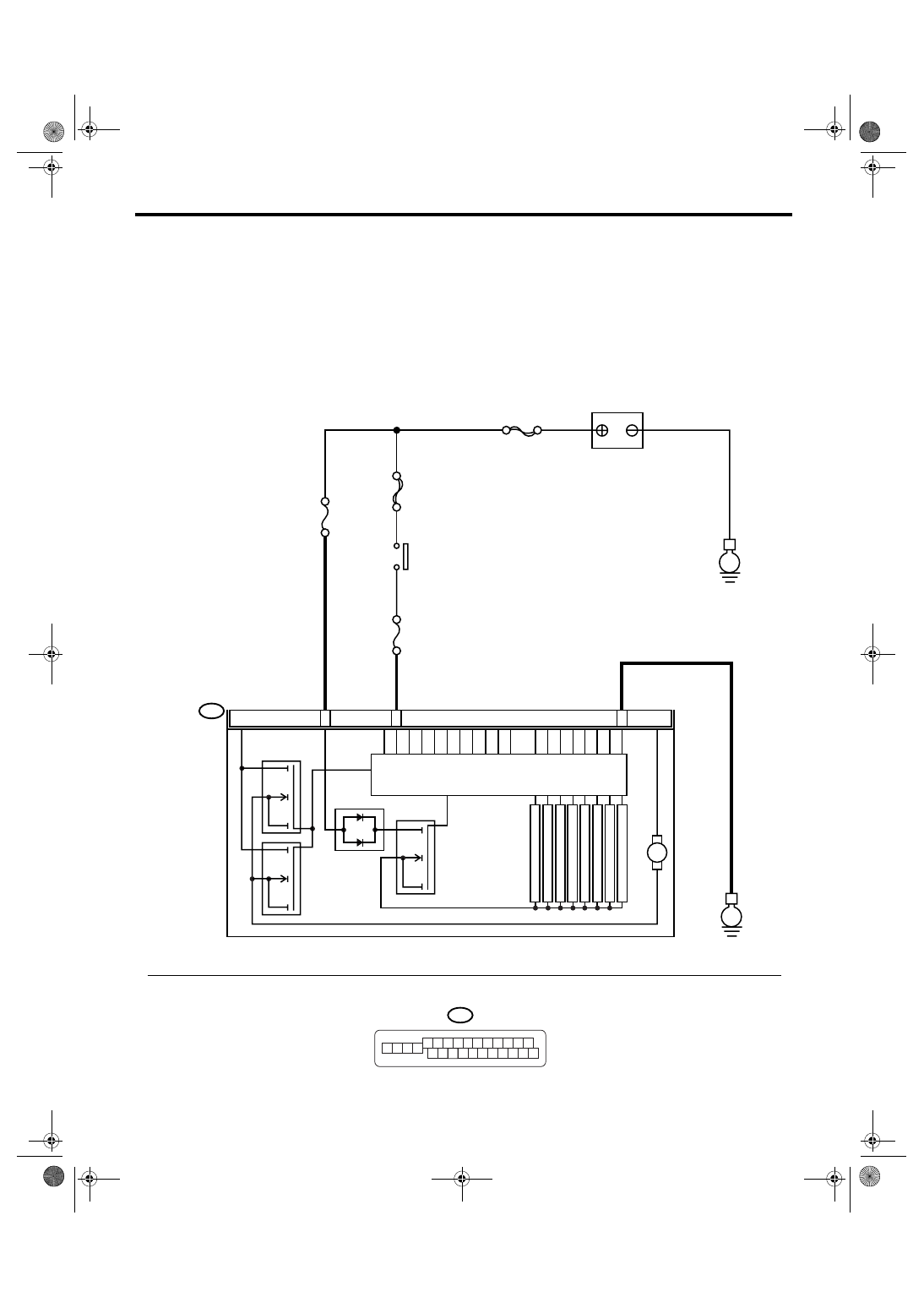
WIRING DIAGRAM:
B301
ABS00686
B301
E
14
15
ABSCM & H/U
18
M
MAIN SBF
SBF-6
No.1
No.33
E
7 8 9 10 11
6
5
4
1
15
14
13
12
2 3
22 23 24 25 26
21
20
19
16 17 18
BATTERY
IGNITION
SWITCH
MOTOR RELAY
VALVE
RELAY
SOLENOID
VALVE
PUMP MOTOR
FL INLET
RL INLET
FR INLET
RR INLET
FL OUTLET
RL OUTLET
FR OUTLET
RR OUTLET
Нет комментариевНе стесняйтесь поделиться с нами вашим ценным мнением.
Текст