Subaru Legacy (2005 year). Service manual — part 756
ABS-9
ABS
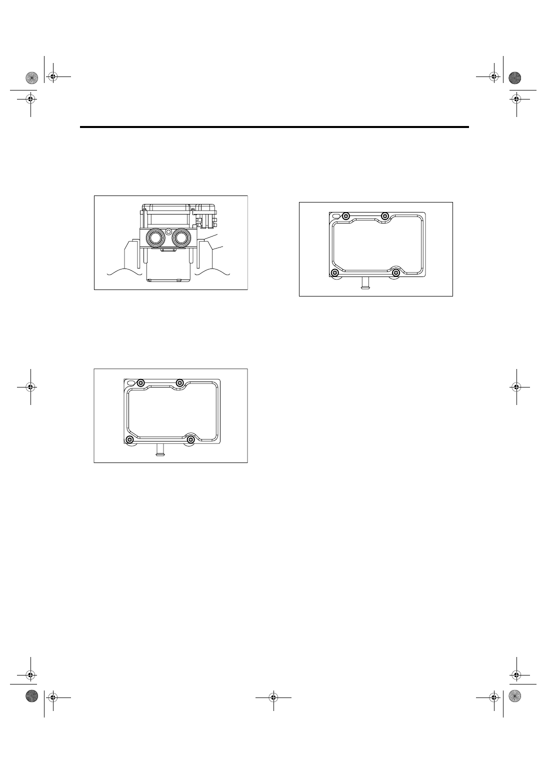
ABS Control Module and Hydraulic Control Unit (ABSCM&H/U)
3) Set the pump motor part of removed ABSCM&H/
U faces down in the vise.
NOTE:
Before securing a part on a vice, place cushioning
material such as wood blocks, aluminum plate or
cloth between the part and vice.
4) Using TORX
®
BIT E5, remove the four screws of
ABSCM.
NOTE:
Always use new screws.
5) Slowly remove the ABSCM upward from H/U.
NOTE:
To prevent damaging of coil part, remove the AB-
SCM straightly from H/U.
6) Ensure there are no dirt or damage on sealing
surface of H/U.
CAUTION:
• Do not clean the ABSCM & H/U with applying
compressed air.
• Do not repair the damages of H/U sealing sur-
face using file or metal scraper. To remove the
sealing, use resin scraper. Do not use the
chemical materials (thinner and etc.).
7) Position the coil of new ABSCM to align H/U
valve.
8) To prevent deforming of ABSCM housing cover,
hold the corner of ABSCM and install it to the H/U
without tilting.
9) Using TORX
®
BIT E5, tighten the screws step-
wise in the order of (1) through (4).
CAUTION:
Always use new screws.
Tightening torque:
1.5 N
⋅
m (0.15 kgf-m, 1.1 ft-lb)
10) Check that there is no foreign matter in aligning
part between ABSCM and H/U.
11) Using TORX
®
BIT E5, tighten the screws step-
wise in the order of (1) through (4) again.
Tightening torque:
3 N
⋅
m (0.3 kgf-m, 2.2 ft-lb)
12) Check that there is no clearance in aligning part
between ABSCM and H/U.
13) Install the ABSCM&H/U to vehicle.
(1) Aluminum plate or etc.
(2) Vise
ABS00430
(1)
(2)
ABS00431
ABS00432
(4)
(2)
(1)
(3)
ABS-10
ABS
ABS Sequence Control
3. ABS Sequence Control
A: OPERATION
1) While the ABS sequence control is performed,
the operation of the hydraulic unit can be checked
using the brake tester or pressure gauge after the
hydraulic unit solenoid valve operation.
2) ABS sequence control can be started by Subaru
Select Monitor.
1. ABS SEQUENCE CONTROL WITH SUB-
ARU SELECT MONITOR
NOTE:
In the event of any trouble, the ABS sequence con-
trol is not operated.
1) Connect the Subaru Select Monitor to data link
connector under the driver’s side instrument panel
lower cover.
2) Turn the ignition switch to ON.
3) Set the Subaru Select Monitor power switch to
ON.
4) Set the Subaru Select Monitor to “Brake Control”
mode.
5) When the “Function check sequence” is select-
ed, the “ABS sequence control” will start.
6) Execute the following operations when the mes-
sage “Press the brake pedal so that the brake ped-
al force is between 100 and 150 kgf” is displayed.
(1) When the brake tester is used, press brake
pedal pad with a force of 1,000 N (102 kgf, 225
lbf).
(2) When using the pressure gauge, press the
brake pedal so as to make the pressure gauge
indicate 3,500 kPa (36 kgf/cm
2
, 511 psi).
7) “Press the [YES] key” will be displayed. Press
the [YES] key.
8) The brake line being operated is displayed on
the Subaru Select Monitor.
ABS-11
ABS
ABS Sequence Control
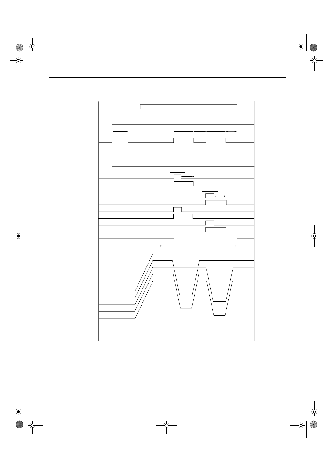
2. CONDITIONS FOR ABS SEQUENCE CONTROL
ABS00561
(1)
(2)
(3)
(4)
(5)
(6)
(7)
(8)
(9)
(10)
(11)
(12)
(13)
(14)
(24)
(25)
(28)
(27)
(26)
V max < 4 km/h (2.5 MPH)
OFF
(16)
(17)
OFF
ON
OFF
ON
OFF
ON
(21)
(19)
OFF
ON
OFF
ON
OFF
ON
OFF
ON
OFF
ON
OFF
ON
OFF
ON
OFF
ON
ON
(15)
(19)
(18)
(19)
V max < 10 km/h (6 MPH)
(16)
(17)
(17)
(16)
(16)
(21)
(19)
(22)
(23)
(20)
ABS-12
ABS
ABS Sequence Control
NOTE:
The control operation starts from point A.
B: SPECIFICATION
1. CONDITIONS FOR COMPLETION OF
ABS SEQUENCE CONTROL
When the following conditions develop, the ABS
sequence control stops and ABS operation is re-
turned to the normal control mode.
1) When the speed of at least one wheel reaches
10 km/h (6 MPH).
2) When the brake pedal is released during ABS
sequence control and the stop light switch goes
OFF.
3) After completion of ABS sequence control.
4) When malfunction is detected.
(1)
All wheel speed
(11)
RR compression valve
(21)
0.4 second
(2)
Ignition key
(12)
RL decompression valve
(22)
Point A
(3)
ABS warning light
(13)
RL compression valve
(23)
Reset
(4)
Stop light switch
(14)
Pump motor
(24)
Master cylinder pressure
(5)
Valve relay
(15)
1.5 seconds
(25)
FL wheel cylinder pressure
(6)
FL decompression valve
(16)
Light OFF
(26)
FR wheel cylinder pressure
(7)
FL compression valve
(17)
Light ON
(27)
RR wheel cylinder pressure
(8)
FR decompression valve
(18)
1.0 second
(28)
RL wheel cylinder pressure
(9)
FR compression valve
(19)
1.4 seconds
(10)
RR decompression valve
(20)
0.6 second
Нет комментариевНе стесняйтесь поделиться с нами вашим ценным мнением.
Текст