Subaru Legacy (2005 year). Service manual — part 272
ME(H4DOTC)-31
MECHANICAL
Engine Assembly
9. Engine Assembly
A: REMOVAL
1) Set the vehicle on a lift.
2) Open the front hood fully and support it with front
food stay.
3) Collect the refrigerant from A/C system. <Ref. to
AC-20, Refrigerant Recovery Procedure.>
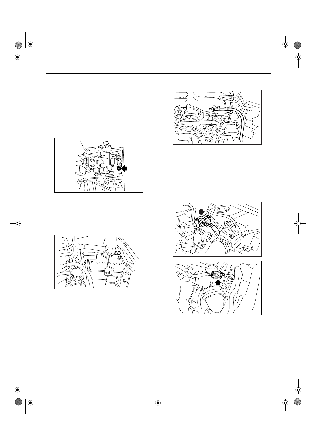
4) Release the fuel pressure.
(1) Remove the fuse of fuel pump from main
fuse box.
(2) Start the engine, and run until it stalls.
(3) After the engine stalls, crank it for 5 seconds
more.
(4) Turn the ignition switch to OFF.
5) Remove the fuel filler cap.
6) Remove the collector cover.
7) Disconnect the ground cable from battery.
8) Remove the radiator from vehicle. <Ref. to
CO(H4DOTC)-19, REMOVAL, Radiator.>
9) Remove the coolant filler tank.
<Ref. to CO(H4DOTC)-31, REMOVAL, Coolant
Filler Tank.>
10) Disconnect the A/C pressure hoses from A/C
compressor.
11) Remove the air intake system.
(1) Remove the intercooler. (DOHC turbo mod-
el) <Ref. to IN(H4DOTC)-12, REMOVAL, Inter-
cooler.>
(2) Remove the air cleaner element and air
cleaner case. <Ref. to IN(H4DOTC)-8, REMOV-
AL, Air Cleaner Case.>
12) Disconnect the following connectors and ca-
bles.
(1) Engine harness connectors
FU-01122
IN-00203
ME-00803
FU-01162
FU-01163
ME(H4DOTC)-32
MECHANICAL
Engine Assembly
(2) Engine ground terminals
(3) Generator connector, terminal and A/C
compressor connector
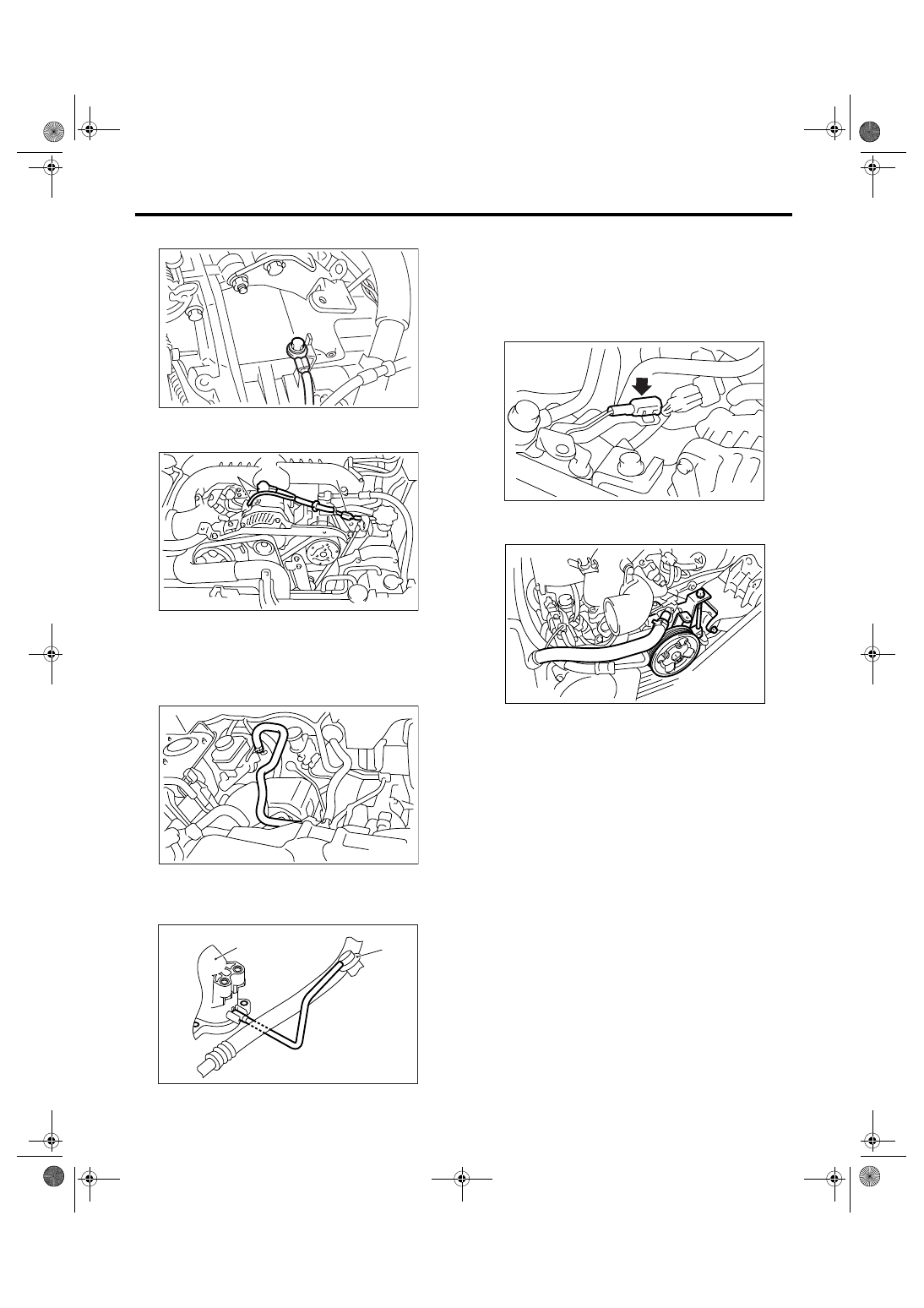
13) Disconnect the following hoses:
(1) Brake booster vacuum hose
(2) Heater inlet and outlet hoses
(3) Remove the hose between intake manifold
(A) and pressure regulator (B).
14) Remove the power steering pump from brack-
et.
(1) Loosen the lock bolt and slider bolt, and re-
move the front side belt. <Ref. to ME(H4DOTC)-
40, FRONT SIDE BELT, REMOVAL, V-belt.>
(2) Disconnect the power steering switch con-
nector.
(3) Remove the power steering pump from en-
gine.
(4) Place the power steering pump onto right
side wheel apron.
15) Remove the linear motion mounting. <Ref. to
ME(H4DOTC)-38, REMOVAL, Linear Motion
Mounting.>
16) Lift-up the vehicle.
17) Remove the center exhaust pipe.
<Ref. to EX(H4DOTC)-6, REMOVAL, Center Ex-
haust Pipe.>
(A) A/C compressor connector
(B) Generator connector and terminal
ME-00028
ME-00804
(A)
(B)
FU-01161
(A)
(B)
ME-00846
ME-00035
ME-00809
ME(H4DOTC)-33
MECHANICAL
Engine Assembly
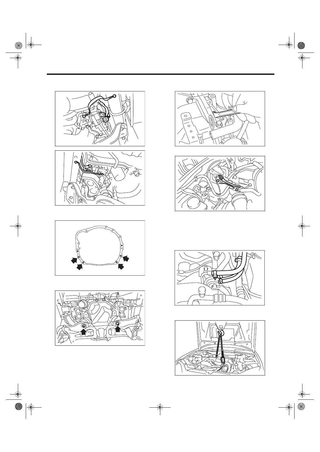
18) Disconnect the oil flow control solenoid valve
connector and ground cable in exhaust side.
19) Remove the nuts which hold lower side of the
transmission to engine.
20) Remove the nuts which install front cushion
rubber onto front crossmember.
21) Separate the torque converter clutch from drive
plate. (AT model)
(1) Lower the vehicle.
(2) Remove the service hole plug.
(3) Remove the bolts which hold torque con-
verter clutch to drive plate.
(4) Remove other bolts while rotating the crank-
shaft using socket wrench.
22) Remove the pitching stopper.
23) Disconnect the fuel delivery hose, return hose
and evaporation hose.
CAUTION:
• Collect fuel from the hose into container.
• Disconnect the hose with its end wrapped
with cloth to prevent fuel from splashing.
24) Support the engine with a lifting device and
wire ropes.
ME-00805
ME-02092
ME-00040
LU-00223
ME-00044
LU-00221
ME-00045
LU-00222
ME(H4DOTC)-34
MECHANICAL
Engine Assembly
25) Support the transmission with a garage jack.
CAUTION:
Doing this is very important because the trans-
mission lowers for its own weight. This work is
also of great importance for facilitating reinstal-
lation.
CAUTION:
Before removing the engine away from trans-
mission, check to be sure no work has been
overlooked.
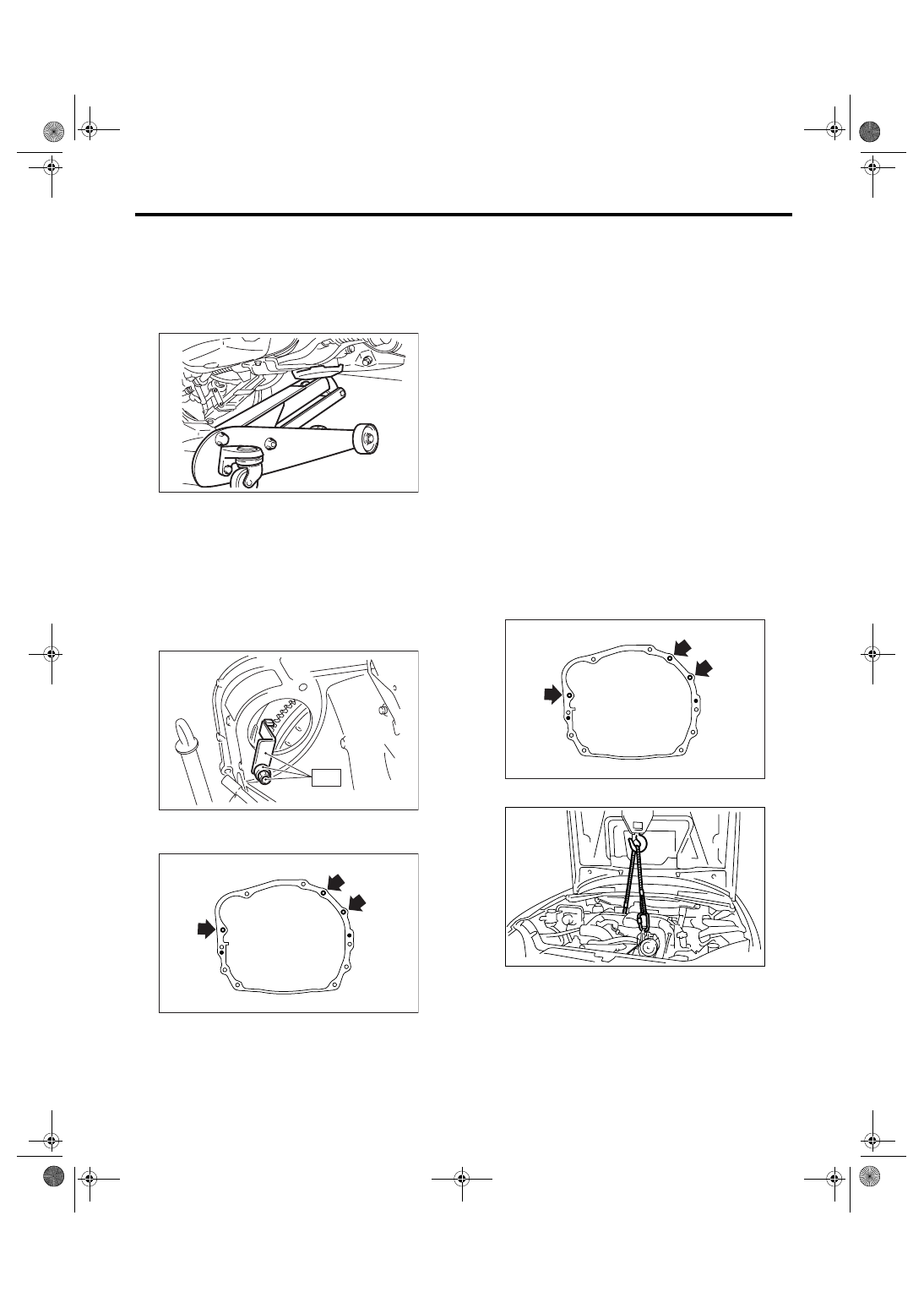
26) Separation of engine and transmission
(1) Remove the starter. <Ref. to SC(H4SO 2.0)-
6, REMOVAL, Starter.>
(2) Install the ST to converter case. (AT model)
ST
498277200
STOPPER SET
(3) Remove the bolts which hold upper side of
the transmission to engine.
27) Remove the engine from vehicle.
(1) Slightly raise the engine.
(2) Raise the transmission with garage jack.
(3) Move the engine horizontally until main
shaft is withdrawn from clutch cover.
(4) Slowly move the engine away from engine
compartment.
NOTE:
Be careful not to damage adjacent parts or body
panels with crank pulley, oil level gauge, etc.
28) Remove the front cushion rubbers.
B: INSTALLATION
1) Install the front cushion rubbers to engine.
Tightening torque:
35 N
⋅
m (3.6 kgf-m, 25.8 ft-lb)
2) Install the engine to transmission.
(1) Position the engine in engine compartment
and align it with transmission.
NOTE:
Be careful not to damage adjacent parts or body
panels with crank pulley, oil pressure gauge, etc.
(2) Apply a small amount of grease to the spline
of main shaft. (MT model)
3) Tighten the bolts which hold upper side of trans-
mission to engine.
Tightening torque:
50 N
⋅
m (5.1 kgf-m, 36.9 ft-lb)
4) Remove the lifting device and wire ropes.
5) Remove the garage jack.
ME-00048
ST
ME-00049
ME-00050
ME-00050
LU-00222
Нет комментариевНе стесняйтесь поделиться с нами вашим ценным мнением.
Текст