Subaru Legacy (2005 year). Service manual — part 1055
WI-13
WIRING SYSTEM
Basic Diagnostic Procedure
F: ABBREVIATION IN WIRING DIA-
GRAMS
Abbr.
Full name
ABS
Antilock Brake System
ACC
Accessory
A/C
Air conditioner
AD
Auto Down
AT
Automatic transmission
AU
Auto Up
A/B
Airbag
A/F
Air/Fuel (Air fuel ratio sensor)
ATF
Automatic transmission fluid
AWD
All Wheel Drive
B, BAT
Battery
CPC
Canister Purge Control
D
Drive Range
DN
Down
E
Ground
ELR
Emergency Locking Retractor
F/B
Fuse & Relay box
FL1.5
Fusible Link 1.5 mm
2
H/L
Headlight
I/F
Interface
IG
Ignition
Illumi.
Illumination
INT
Intermittent
LH
Left Hand
Lo
Low
M
Motor
M/B
Main fuse box
MG
Magnet
Mi
Middle
MT
Manual transmission
N
Neutral Range
OCV
Oil flow control solenoid valve
OP
Optional Parts or Open
P
Parking Range
PASS
Passing
R
Reverse Range
RH
Right Hand
SBF
Slow Blow Fuse
ST
Starter
SW
Switch
TGV
Tumble generated valve
U, UP
Up
VDC
Vehicle Dynamics Control
VVL
Variable Valve Lift
WASH
Washer
WI-14
WIRING SYSTEM
Working Precautions
2. Working Precautions
A: PRECAUTIONS WHEN WORKING
WITH THE PARTS MOUNTED ON
THE VEHICLE
1) When working under a vehicle which is jacked-
up, always be sure to use rigid rack.
2) The parking brake must always be applied dur-
ing working. Also, in automatic transmission vehi-
cles, keep the select lever set to the P (Parking)
range.
3) Be sure the workshop is properly ventilated
when running the engine. Further, be careful not to
touch the belt or fan while the engine is operating.
4) Be careful not to touch hot metal parts, especial-
ly the radiator and exhaust system immediately af-
ter the engine has been turned off.
B: PRECAUTIONS IN TROUBLE DI-
AGNOSIS AND REPAIR OF ELEC-
TRIC PARTS
1) The battery cable must be disconnected from
the battery’s (
−) terminal, and the ignition switch
must be set to the OFF position, unless otherwise
required by the diagnostics.
2) Securely fasten the wiring harness with clamps
and slips so that the harness does not interfere with
the body end parts or edges and bolts or screws.
3) When installing parts, be careful not to catch
them on the wiring harness.
4) When disconnecting a connector, do not pull the
wires, but pull while holding the connector body.
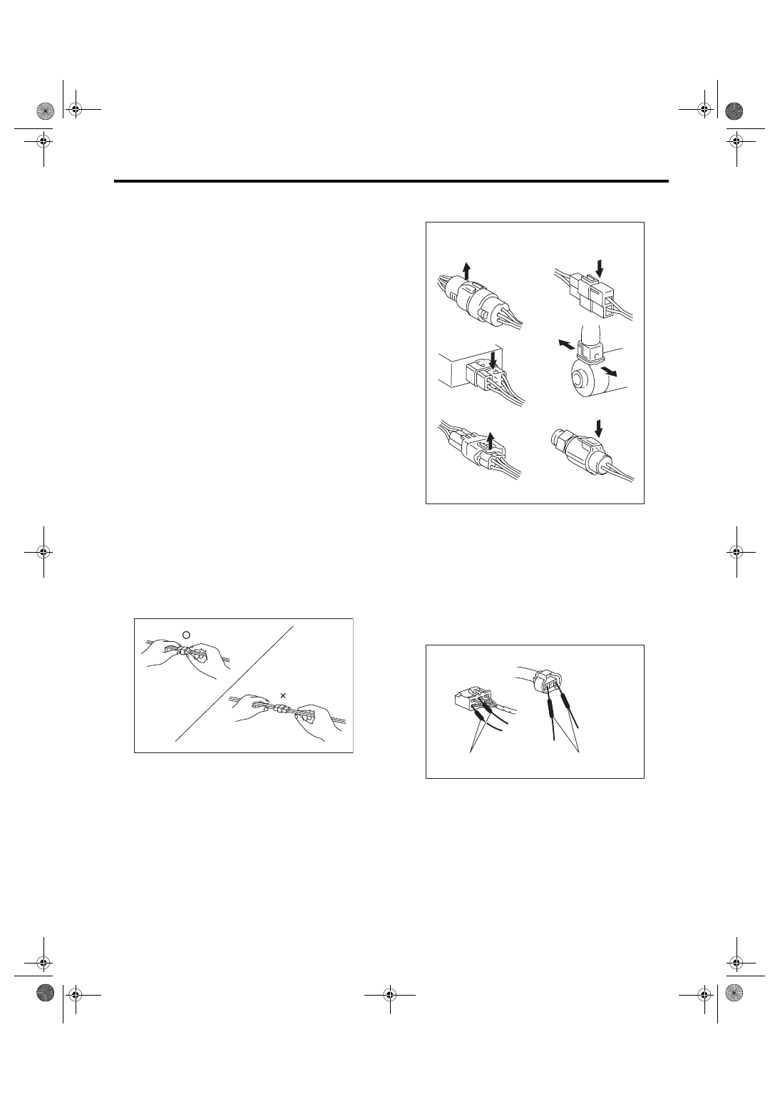
5) Some connectors are provided with a lock. One
type of such a connector is disconnected by push-
ing the lock, and the other, by moving the lock up.
In either type the lock shape must be identified be-
fore attempting to disconnect the connector.
To connect, insert the connector until it snaps and
confirm that it is tightly connected.
6) When checking continuity between connector
terminals, or measuring voltage across the terminal
and ground, always contact tester probe(s) on ter-
minals from the wiring connection side. If the probe
is too thick to gain access to the terminal, use “mini”
test leads.
To check water-proof connectors (which are not
measurable from the wiring side), contact test
probes on the terminal side. Be careful not to bend
or damage the terminals.
7) Sensors, relays, electrical unit, etc., are sensi-
tive to strong impacts.
Handle them with care so that they are not dropped
or mishandled.
WI-02757
WI-02758
Example
LIFT
LIFT
PUSH
PUSH
PUSH
WI-02759
Tester probes
"Mini" test leads
WI-15
WIRING SYSTEM
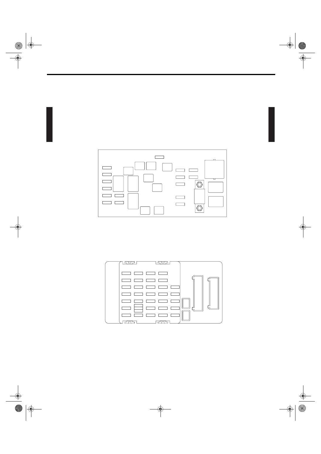
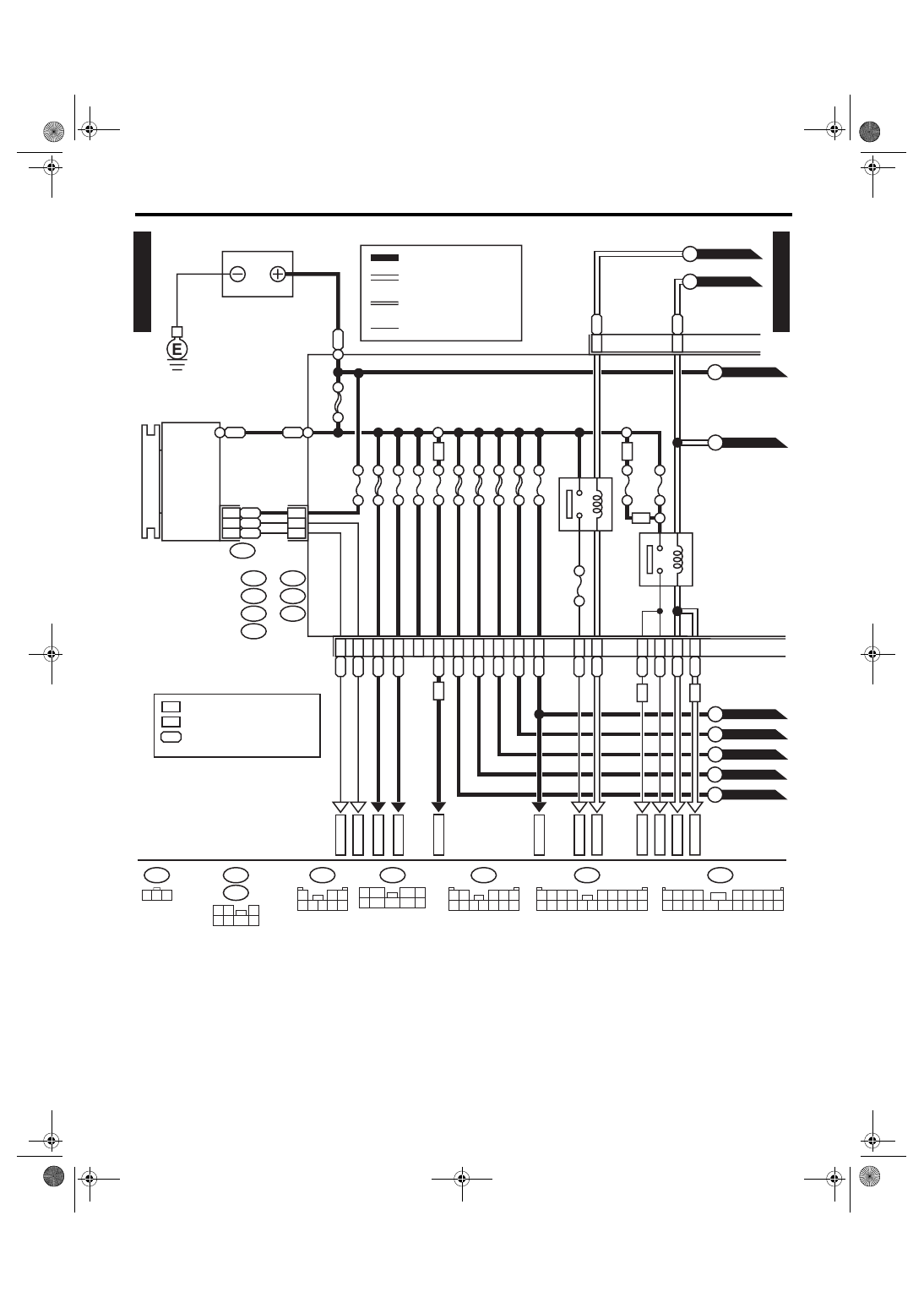
Power Supply Circuit
3. Power Supply Circuit
A: WIRING DIAGRAM
1. LHD MODEL
P-SUP(L)-01
P-SUP(L)-01
WI-06861
MAIN FUSE BOX (M/B)
FUSE & RELAY BOX (F/B)
H/L
RELAY
RH
MAIN
FAN
RELAY-1
MAIN
SBF
H/L
RELAY
LH
NO. 8
NO. 11
NO. 12
NO. 13
NO. 14
NO. 15
NO. 16
NO. 27
NO. 28
NO. 29
NO. 30
NO. 31
NO. 32
NO. 33
NO. 20
NO. 21
NO. 22
NO. 23
NO. 24
NO. 25
NO. 26
NO. 13
NO. 14
NO. 15
NO. 16
NO. 17
NO. 18
NO. 19
NO. 6
NO. 7
NO. 8
NO. 9
NO. 10
NO. 11
NO. 12
NO. 1
NO. 2
NO. 3
NO. 4
NO. 5
NO. 9
NO. 10
NO. 3
NO. 4
NO. 1
NO. 2
NO. 5
NO. 6
NO. 7
SBF-8
SBF-6
SBF-2
SBF-3
SBF-4
SBF-7
SBF-5
SBF-1
HORN
RELAY
R.DEF
RELAY
TAIL
RELAY
WI-16
WIRING SYSTEM
Power Supply Circuit
P-SUP(L)-02
P-SUP(L)-02
WI-06862
P-SUP(L)-05
B
P-SUP(L)-05
A
P-SUP(L)-03
C
P-SUP(L)-04
I
P-SUP(L)-04
H
P-SUP(L)-03
D
P-SUP(L)-05
G
P-SUP(L)-05
F
P-SUP(L)-04
E
W
W
F26
B145
G:
1 2 3
B186
H:
(BROWN)
B144
D:
(BLUE)
F35
C:
A:
1
2 3
4 5 6 7 8
1 2
3 4 5
6 7 8 9 10 11 12
F37
1 2
3
4 5
6
7
1
5
7
6
2
8
3
4
9
1 2 3 4
5 6 7 8 9
10 11 12 13 14
15 16 17 18 19 20
B: B143
1 2 3 4
5 6 7 8 9
10 11 12 13 14 15 16 17 18 19 20
F36
E:
(BROWN)
(GREEN)
H4
H4
WR
BR
BW
2
1
BR
3
B1
B7
C10
GENERATOR
MAIN FUSE BOX (M/B)
BATTERY
MB-2
MB-10
F26
MB-4
MB-29
MB-1
MB-9
MB-8
MB-7
MB-6
A7
A9
A19
NO. 4 25A
MAIN
SBF 120A
NO. 2 25A
NO. 8 20A
NO. 3 25A
NO. 5 20A
NO. 1 30A
NO. 16 7.5A
NO. 10 25A
SBF-1 50A
SBF-8 50A
SBF-6 50A
SBF-3 50A
SBF-2 50A
LR
E5
E6
RL
G7
H8
GOr
GB
W
H4
B19
ALT-2
ALT-1
MAIN FAN
RELAY 1
REAR DEFOGGER RELAY
F37
A:
B143
B:
F35
C:
B144
D:
F36
E:
B145
G:
B186
H:
LR
D9
GD
3
WD
2
RD
6
RW
E3
D1
RY
D5
WR
D7
WB
B11
LD
8
MB-5
WR
RL
VG
H4
H4
1
*
H6
H6
: 6-CYLINDER ENGINE MODEL
: 4-CYLINDER ENGINE MODEL
: 4-CYLINDER ENGINE MODEL
: 6-CYLINDER ENGINE MODEL
1
*
H6
H4
: YG
: LW
OTHER CURRENT
BATTERY CURRENT
CURRENT FROM IGNITION
SWITCH “IG” TERMINAL
CURRENT FROM IGNITION
SWITCH “ACC” TERMINAL
Нет комментариевНе стесняйтесь поделиться с нами вашим ценным мнением.
Текст