Subaru Legacy (2005 year). Service manual — part 1053
WI-5
WIRING SYSTEM
Basic Diagnostic Procedure
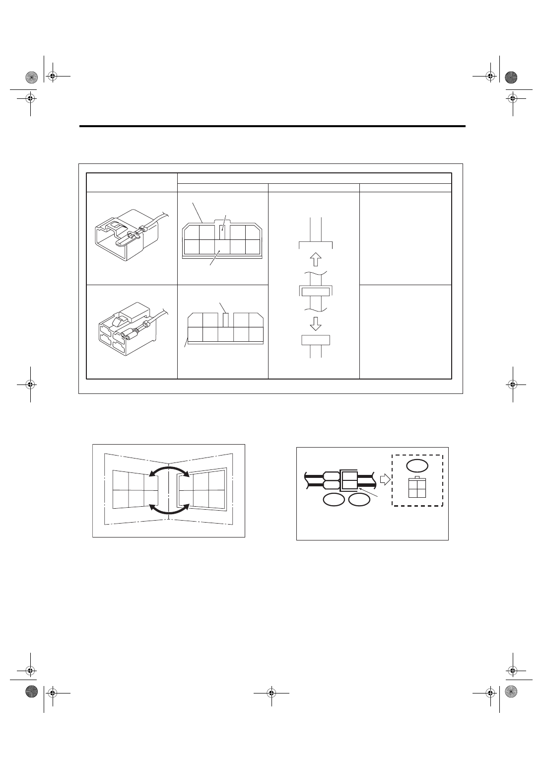
• The number of poles or pins, presence of a lock are indicated in the sketch of each connector. In the
sketch, the highest pole number refers to the number of poles which the connector has. For example, the
sketch of the connector shown in figure indicates the connector has 9 poles.
• When one set of connectors is viewed from the
front side, the pole numbers of one connector are
symmetrical to those of the other. When these two
connectors are connected as a unit, the poles
which have the same number are joined.
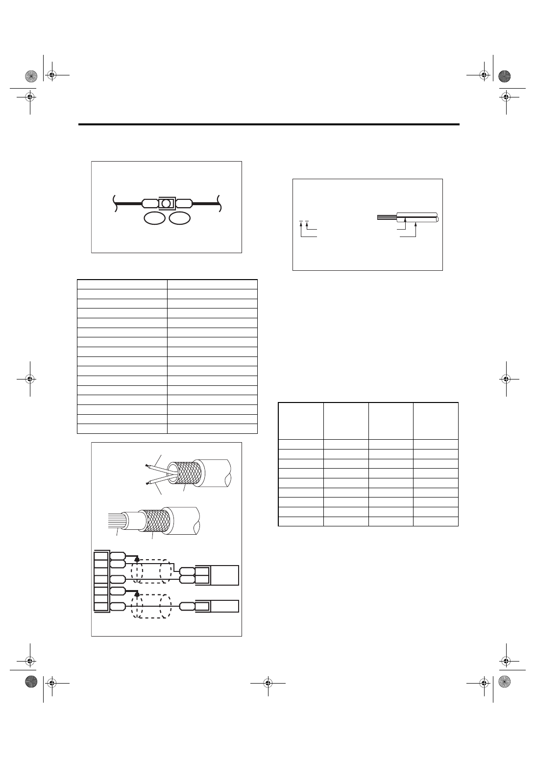
• WIRING DIAGRAM:
The connectors are numbered along with the num-
ber of poles, external colors, and mating connec-
tions in the accompanying list.
• The sketch of each connector in the wiring dia-
gram usually shows the (A) side of the connector.
The relationship between the wire color, terminal
number and connector is described in the figure.
NOTE:
A wire which runs in one direction from a connector
terminal sometimes may have a different color from
that which runs in the other direction from that ter-
minal.
WI-02747
Connector used in vehicle
Sketch
Symbol
Number of poles
Numbered in order from upper
right to lower left.
Numbered in order from upper
left to lower right
Connector shown in wiring diagram
Double frames
Indicates a lock
is included.
Indicates the number of poles.
4
3
2
1
9
8
7
6
5
Indicates a lock is included.
Single frame
1
2
3
4
5
6
7
8
9
WI-00107
1
1
2
2
3
3
4
4
5
5
6
6
WI-02748
Wire color :
BR (No. 1 terminal)
RW (No. 3 terminal)
i2
3 4
1 2
BR
RW
i2
F4
1
3
(A)
WI-6
WIRING SYSTEM
Basic Diagnostic Procedure
• In the wiring diagram, connectors which have no
terminal number refer to one-pole types. Sketches
of these connectors are omitted intentionally.
• The following color codes are used to indicate
the colors of the wires.
• The wire color code, which consists of two letters
(or three letters including Br or Lg), indicates the
standard color (base color of the wire covering) by
its first letter and the stripe marking by its second
letter.
• The table lists the nominal sectional areas and
allowable currents of the wires.
CAUTION:
When replacing or repairing a wire, be sure to
use the same size and type of the wire which
was originally used.
NOTE:
• The allowable current in the table indicates the
tolerable amperage of each wire at an ambient
temperature of 40
°C (104°F).
• The allowable current changes with ambient
temperature. Also, it changes if a bundle of more
than two wires is used.
Color code
Color
L
Blue
B
Black
Y
Yellow
G
Green
R
Red
W
White
Br
Brown
Lg
Light green
Gr
Gray
P
Pink
Or
Orange
Sb
Light blue
V
Purple
SA
Sealed (Inner)
SB
Sealed (Outer)
WI-00109
B
B
B15
F10
WI-00110
YL
2
YG
1
SB
10
YL
9
YG
8
SA
1
SB
22
SA
20
YG
YL
SB
SB
SA
Nominal sec-
tional area
No. of
strands/
strand diam-
eter
Outside
diameter of
wiring
Allowable
current
Amps/
40
°C (104°F)
mm
2
mm
0.3
7/0.26
1.8
7
0.5
7/0.32
2.2 (or 2.0)
12
0.75
30/0.18
2.6 (or 2.4)
16
0.85
11/0.32
2.4 (or 2.2)
16
1.25
16/0.32
2.7 (or 2.5)
21
2
26/0.32
3.1 (or 2.9)
28
3
41/0.32
3.8 (or 3.6)
38
5
65/0.32
4.6 (or 4.4)
51
8
50/0.45
5.5
67
WI-03797
Y B
Black
Marking color :
Reference color :
Yellow
WI-7
WIRING SYSTEM
Basic Diagnostic Procedure
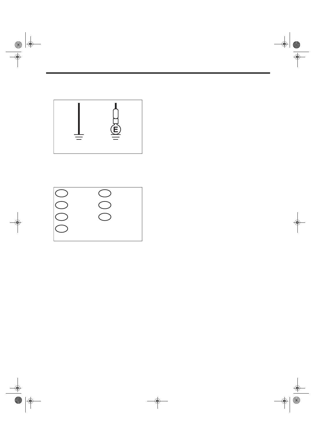
• Each unit is either directly grounded to the body
or indirectly grounds through a harness ground ter-
minal. Different symbols are used in the wiring dia-
gram to identify the two grounding systems.
• The ground points shown in the wiring diagram
refer to the following:
NOTE:
All wiring harnesses are provided with a ground
point which should be securely connected.
WI-02750
Direct ground
Indirect terminal
ground
B
WI-03791
: ABS GROUND
GA
: AIRBAG GROUND
GAB
: BODY GROUND
GB
: ENGINE GROUND
GE
: RADIO GROUND
GR
: VDC GROUND
GV
: REAR DEFOGGER GROUND
GD
S903.fm 7 ページ 2007年12月3日 月曜日 午後1時59分
WI-8
WIRING SYSTEM
Basic Diagnostic Procedure
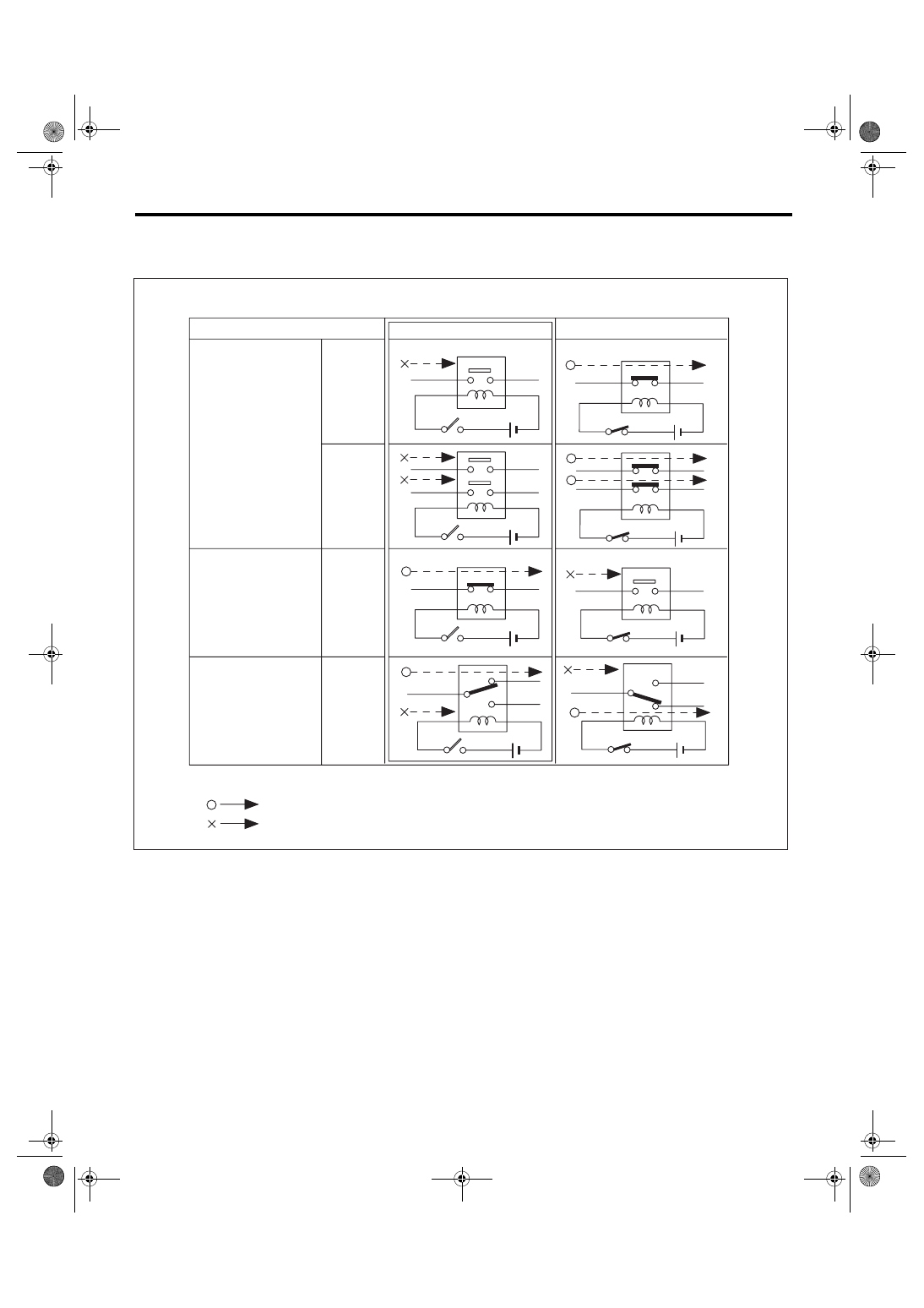
• Relays are classified as normally-open or normally-closed.
The normally-closed relay has one or more contacts. The wiring diagram shows the relay mode when the en-
ergizing circuit is OFF.
Relay type
4-pole
6-pole
4-pole
6-pole
Normally-open type
Normally-closed type
Mixed type
Key to symbols:
: Current flows.
: Current does not flow.
Energizing circuit OFF
Energizing circuit ON
WI-02752
Нет комментариевНе стесняйтесь поделиться с нами вашим ценным мнением.
Текст